The need for 3D printed enclosures shows up all the time in product design. But precision is tricky: if you leave too much tolerance, parts end up loose; if you leave too little, they simply won’t fit.
3D printer accuracy is as unpredictable as the weather. Even a slight change in ambient humidity on the same machine can yield prints with oversized edges or undersized edges. Those two conditions on both top and bottom covers multiply into four possible mismatches. Designs with many mating points see the risk of failed assembly grow exponentially.
You might think, “Great, I'll just set zero clearance and sand each piece down by hand.” But once you’re making more than ten parts, either your hands or your sanding tool will overheat first.
Is there no workaround? In fact, if you’re willing to tweak your CAD, you can print ten, a hundred, or even ten thousand units and still hit consistent, reliable fits every time.
Smooth out The Corners
In manufacturing, life isn’t all sharp 90° angles, most consumer products use fillets or chamfers. Printing a hard 90° corner is like taking a high-speed car into a tight right-angle: you risk a blob of excess material or a shrunk corner, both introduce dimensional error.
Instead, replace that crisp 90° with a smooth arc. This single change dramatically cuts down corner-related size variations.

Image Copyright © 3DSPRO. All rights reserved.
Between the two examples above, the rounded-corner design on the right not only snaps together more easily but also prints more reliably.
Rather Than A Strict Two-State Fit, Let It Slide in
Beyond corner errors, another effective trick is to make the mating edge a sloped surface.
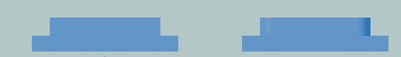
Image Copyright © 3DSPRO. All rights reserved.
Where possible, reduce the top face slightly and change the mating geometry to a trapezoid. It’s like adding a guide rail to a drawer: the sloped surface guides the two parts to “slide” into the correct position instead of jamming. Even with small dimensional errors, the angled face provides a buffer, turning assembly from a binary “fits/doesn’t fit” into a forgiving range of “loose to tight but insertable.”
Leverage Part Flexibility for a Snug Fit
If fillets and chamfers are your basics, compliant design is the next level. The principle: since absolute dimensional precision is impossible, design parts to “compromise” by flexing and adapting to each other.
• Thin walls and reduced contact areas. Convert large, solid contact zones into thinner walls or minimal touch points. For example, hollow out a solid cover or clip off the base’s four inner corners. Fewer contact areas mean less friction and looser tolerance requirements.
• Built-in elastic features. Instead of two rigid halves butting together, give one half a little springiness. A few proven tricks:
• Star-shaped ribs. Inside the cover, add a star of ribbing so only the rib tips touch the base’s inner wall. Each rib acts as a tiny cantilever beam, bending inward to soak up errors and deliver just the right clamping force.
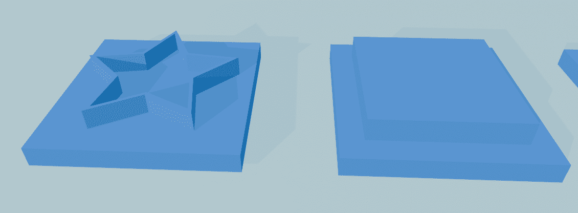
Image Copyright © 3DSPRO. All rights reserved.
• Corner slots. Slice a narrow slot at each base corner, turning the rigid corner into a springy arm. As the cover goes in, these corners flex outward, gripping like internal springs.
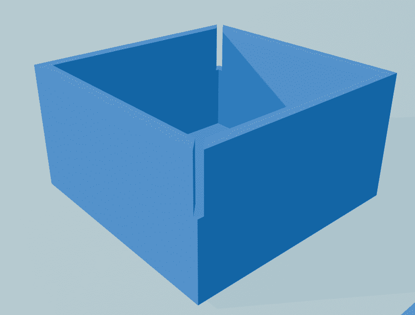
Image Copyright © 3DSPRO. All rights reserved.
These features tap into the material’s natural elasticity, giving you a firm hold without sacrificing structural stability.
Designs That Take Advantage of 3D Printing — Grip Fins
When snaps, screws, or post-print tweaks aren’t an option, try grip fins—only truly practical with additive manufacturing. On the mating surface, design a row of independent, angled “fin” arms.
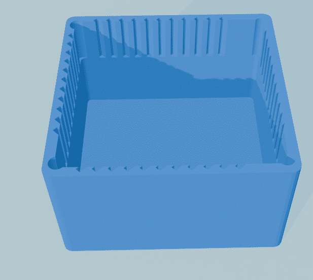
Image Copyright © 3DSPRO. All rights reserved.
Each fin behaves like a micro-spring. As you insert the cover, the fins compress slightly, creating a uniform, continuous pressure all around.
By distributing tolerance compensation across dozens of tiny fins, you can accommodate large overall dimensional variations. Whether your part comes out 0.1 mm oversize or 0.1 mm undersize, the fins simply compress more or less to give you the same satisfying snap fit. For mass production, grip fins minimize material use, maintain consistent feel across batches, and—thanks to 3D printing—add almost no extra processing time.
Summary
To solve assembly problems caused by print accuracy fluctuations, start by optimizing the CAD model instead of endlessly tweaking print settings. Designing for tolerance and including forgiving geometry ensures that parts will assemble reliably across different print conditions. In short, design for manufacturing can make your parts tolerant, adaptive, and easy to assemble.
**Reference:
1. https://www.youtube.com/watch?v=XKrDUnZCmQQ
2. Design ideas and basics are based on FDM.
 23
23