Understanding Interlocking Parts
Interlocking parts are components designed to connect or fit together in a way that prevents separation without deliberate force or motion. They rely on geometry, friction, or mechanical features to hold assemblies together.
Benefits of Interlocking Parts
• Ease of assembly: No need for glue, screws, or external fasteners.
• Reusability: Parts can be disassembled and reused.
• Functionality: Enables moving mechanisms like hinges or sliding rails.
• Customization: Modular systems allow users to mix and match components.
Applications
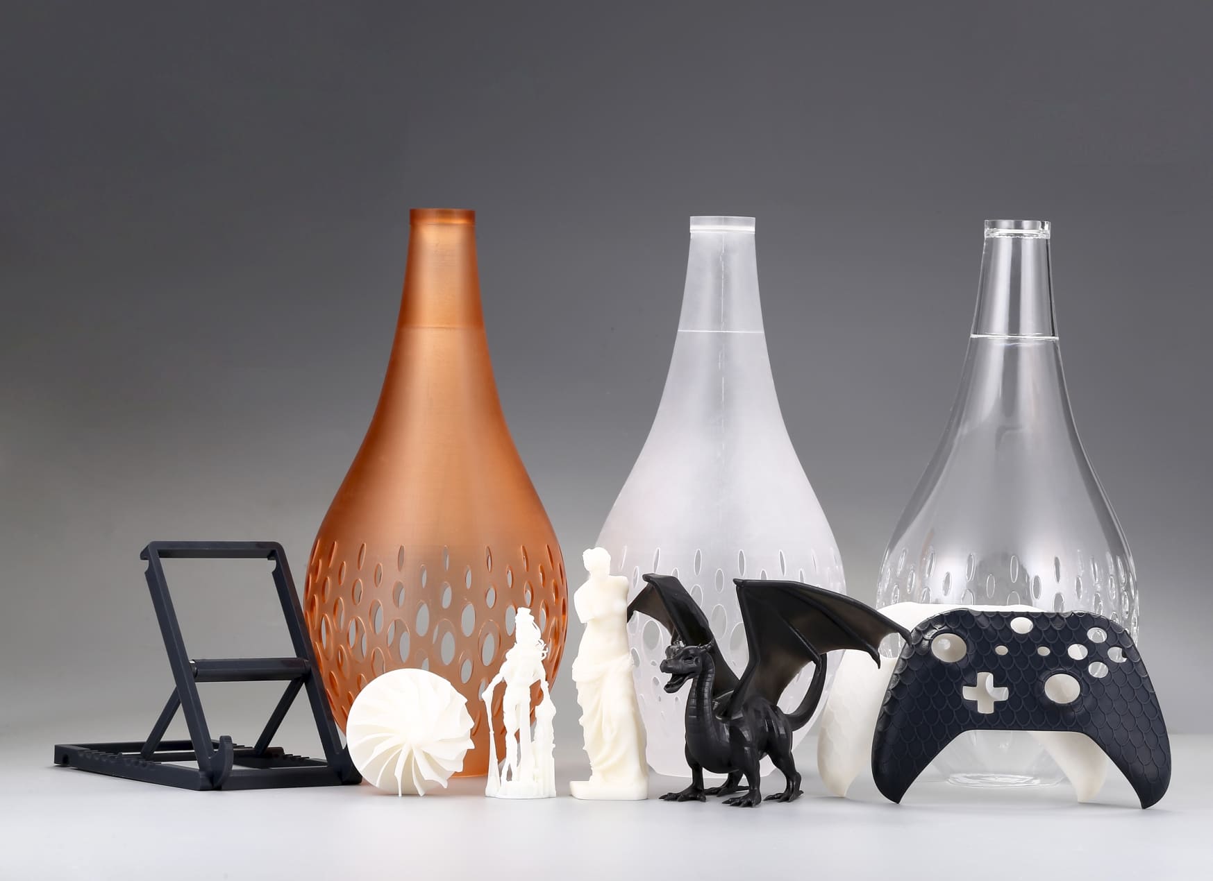
• Consumer products: Toys, puzzles, modular organizers.
• Engineering prototypes: Snap-fit housings, enclosures, and mechanical joints.
• Architecture and design: Scaled models with modular connections.
• Furniture and decor: Flat-pack designs that lock together without tools.
Image Copyright © 3DSPRO Limited. All rights reserved.
Key Design Considerations
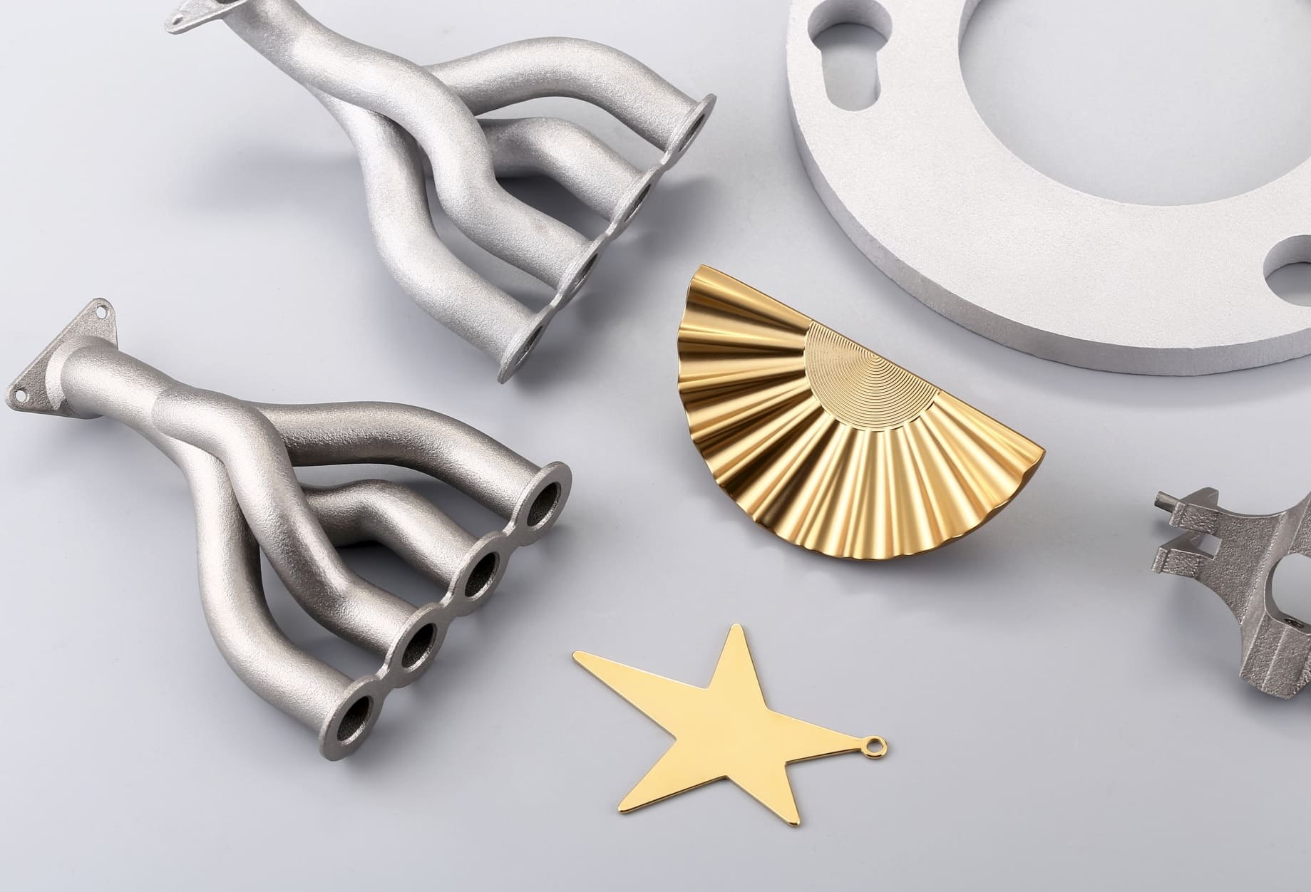
1. Material Choice
• Thermoplastics (FDM): PLA (rigid), ABS (tough, flexible), PETG (balanced), TPU (elastic).
• Resins (SLA/DLP): High precision, smooth surfaces, but brittle unless using toughened resins.
• Powder polymers (SLS/MJF): Nylon (PA12, PA11) offers strength, flexibility, and durability.
• Metals (SLM/DMLS): Stainless steel, titanium, aluminum, extremely strong but require larger tolerances due to shrinkage and post-processing.
2. Printer Capabilities
• FDM: Resolution limited by nozzle size; tolerances ~0.2–0.5 mm.
• SLA/DLP: Very high resolution; tolerances ~0.1–0.2 mm.
• SLS/MJF: Good accuracy for functional parts; tolerances ~0.2–0.4 mm.
• Metal powder-bed fusion: Shrinkage and heat distortion require ~0.5–1 mm clearance.
3. Strength vs. Flexibility
• Plastics: Balance between rigidity and elasticity.
• Resins: Precise but brittle unless reinforced.
• Polymers (nylon): Excellent fatigue resistance for repeated interlocks.
• Metals: Strongest, but interlocks must account for machining or finishing.
4. Print Orientation
• FDM: Layer adhesion affects snap-fit strength.
• SLA: Orientation impacts support removal and surface finish.
• SLS/MJF: Orientation is less critical, but affects powder removal.
• Metal fusion: Orientation impacts residual stress and post-machining.
Designing for Tolerances
Typical Tolerance Ranges
|
Technology |
Clearance Range |
Notes |
|
FDM |
0.2–0.5 mm |
Depends on nozzle size and calibration |
|
SLA/DLP |
0.1–0.2 mm |
High precision, but resin brittleness matters |
|
SLS/MJF |
0.2–0.4 mm |
Nylon parts allow flexible fits |
|
Metal (SLM/DMLS) |
0.5–1 mm |
Accounts for shrinkage, heat distortion, and post-machining |
Strategies
• Test prints: Calibration pieces with varying clearances.
• Iterative design: Adjust based on results.
• Parametric CAD: Easily modify tolerances.
• Post-processing: Sanding, machining, or polishing to refine fits.
Types of Interlocking Mechanisms
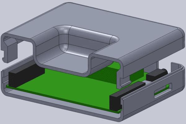
1. Snap-Fit Joints
• Plastics (FDM, SLS): Flexible arms or hooks.
• Resins (SLA): Possible but brittle—use reinforced geometries.
• Metals: Rare due to rigidity; better suited for sliding or bolted interlocks.
2. Rotational Locks
• Hinges: Common in plastics and resins.
• Twist-to-lock: Effective in polymers and metals with larger tolerances.
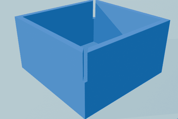
3. Sliding Interlocks
• Dovetail joints: Excellent for nylon (SLS/MJF) and metals.
• Rails and grooves: Work across all technologies, but require tolerance tuning.
4. Puzzle-Style Connections
• Geometric interlocks: Best in high-precision SLA or nylon SLS.
• Decorative assemblies: Ideal for resin-based printing.
5. Hybrid Mechanisms
• Combining sliding with snap-fit for added security.
• Example: Nylon dovetail with a flexible latch.
CAD Design Best Practices
1. Use Parametric Modeling
• Allows easy adjustment of tolerances and dimensions.
• Facilitates iterative testing without rebuilding models.
2. Add Chamfers and Fillets
• Chamfers: Help guide parts into place.
• Fillets: Reduce stress concentrations and improve durability.
3. Consider Assembly Direction
• Design interlocks to assemble in one direction.
• Avoid requiring complex maneuvers that frustrate users.
4. Account for Print Orientation
• Align interlocking features with layer lines for strength.
• Minimize support material in critical areas.
5. Prototype Digitally
• Use CAD simulations to test the assembly before printing.
• Check for interference or impossible geometries.
6. Document Design Parameters
• Record tolerance values, material choices, and orientation.
• Helps future iterations and collaboration.
Common Mistakes to Avoid
1. Ignoring Printer Limitations
• Designing features smaller than the printer can resolve.
• Solution: Match design detail to printer resolution.
2. Forgetting Shrinkage and Warping
• Materials like ABS shrink after cooling.
• Solution: Adjust dimensions or use materials with low shrinkage.
3. Overcomplicating Interlocks
• Complex geometries may be unnecessary.
• Solution: Start simple—snap-fit or dovetail joints often suffice.
4. Neglecting Ergonomics
• Interlocks that require excessive force frustrate users.
• Solution: Design for ease of assembly and disassembly.
5. Skipping Test Prints
• Assuming tolerances will work without testing.
• Solution: Always print calibration pieces before final designs.
6. Poor Orientation Choices
• Printing interlocks in weak directions leads to breakage.
• Solution: Orient parts to maximize strength along stress lines.
 1
1