Well-designed snap-fits let you build enclosures, battery doors, clips, and many other assemblies without screws or adhesives.
Types of Snap-Fits
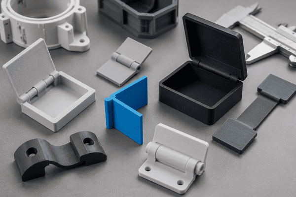
Cantilever Snap-Fit
The most common for 3D printing: a flexible beam (cantilever) with a hook or lip that deflects during assembly and springs back to lock. Good for flat enclosures, battery doors, and clips. Simple to design and easy to print.
Annular / Circumferential Snap
Used when you need a ring-like lock (e.g., lids that snap onto cylindrical housings). Forces are distributed around the circumference, so retention is high; design for symmetric deflection.
Torsional Snap-Fit
Relies on twisting a feature into place (think twist-lock caps). Useful when a small rotation gives positive engagement and when cantilever motion is hard to implement.
Living-Hinge + Catch
Combines a thin flexible hinge and a small catch. Useful for lids and covers where you want repeated opening without separate hinges.
Hooked/Undercut Snap
Features that use undercuts or hooked geometry to lock into mating parts. Strong retention but requires careful design to avoid exceeding material strain limits during assembly.
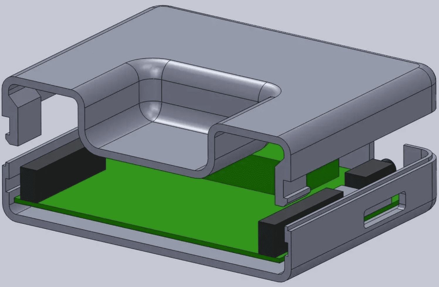
Image Source: Formlabs
Core Design Principles
1. Understand the Beam
For cantilevers, the beam’s effective length, thickness, and width determine how much it deflects under a given load. Longer, thinner beams are more flexible; shorter, thicker beams are stiffer. Use conservative geometry for brittle materials (e.g., PLA) and more aggressive, thinner beams for flexible materials (e.g., TPU, Nylon).
2. Clearance vs Interference
Decide how much interference (the amount the snap must compress) you want. Typical small-part interference for hobby FDM printers is in the order of 0.1–0.3 mm per mating face, but varies by nozzle, printer accuracy, and material. If in doubt, design modular test coupons.
3. Reduce Stress Concentrations
Add generous fillets at the outs and avoid sharp corners where the snap meets the body. A rounded root distributes strain and dramatically reduces fracture risk.
4. Orientation for Peel, Not Shear
Snaps fail less often when loaded in peel (sequential bending) rather than pure shear. Aim to design the assembly direction so the snap peels out instead of pushing straight off.
5. Layer Direction Matters
3D printing creates anisotropy: parts are generally weaker between layers. Orient cantilevers so the layer lines support the bending direction you need (either to maximize strength or to allow controlled flexing). As a rule: if you want the snap to be stiff, orient layers perpendicular to the bending plane; if you want more flex, orient layers parallel to the beam.
6. Material Selection
PLA is stiff but brittle; choose conservative radii and thicker beams. PETG and ABS are tougher and tolerate thinner cantilevers. Nylon and TPU are ideal for high-cycle flexible snaps but need different print settings (drying, higher temps, slower speeds).
7. Add Strain Relief and Ramps
A small tapered ramp on the contact face eases assembly forces by gradually engaging the snap instead of forcing all the strain at once.
CAD and Modeling Workflow
1. Parametric Design
Build snaps parametrically (dimension-driven) so you can quickly tweak beam length, thickness, lip height, and interference, which makes A/B testing and variant generation trivial.
2. Use Boolean Operations Carefully
Boolean cuts can produce messy meshes when exported. For best results, model snaps with solid geometry (fillets, chamfers) rather than relying on imported triangulated meshes.
3. Add Alignment Features
Add guide chamfers, alignment pins, or tapered bosses to make assembly forgiving and to prevent mis-engagement that stresses the snap.
4. Export with Controlled Resolution
When exporting to STL, use enough resolution so small fillets and radii survive meshing. But avoid excessively fine meshes that bloat file size.
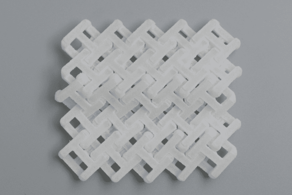
5. Create A Test Panel
Create a small panel model with a range of different snap-fit variations: varying beam thicknesses, lengths, and interference values. Print test pieces as a first iteration to validate your assumptions before proceeding with final assembly.
Finishing, Assembly and Lifecycle Tips
Light sanding or a quick deburr on the mating faces cleans up stringing or rough edges that increase insertion force. For some materials, a gentle anneal improves toughness and reduces internal stresses, and check material guidance before annealing.
Lubrication & Coatings
A dry PTFE spray or silicone lubricant reduces wear and insertion force for high-cycle snaps. Avoid oils that degrade plastics.
Controlled Assembly
If assembly requires high force, use a clamp or press to avoid applying side torque that could break the clip. For field-replaceable parts, design in a clear release feature or tab.
Design for Lifecycle
Consider the number of cycles a clip must withstand. If the number of cycles exceeds 100, choose a tougher material and a rounded geometry. For permanent components, design in discrete failure points or sacrificial clips that can be replaced without scrapping the entire part.
Troubleshooting Checklist
|
Problem |
Likely Cause |
Quick Fix |
|
Snap breaks on first use |
Sharp corners, brittle material, weak orientation |
Add fillet at root, increase thickness, change print orientation, switch to PETG/Nylon |
|
Too stiff / hard to assemble |
Too much interference, short/thick beam |
Reduce interference by 0.05–0.2 mm, add ramp, lengthen beam |
|
Loose after a few cycles |
Material creep (PLA), low retention lip |
Use Nylon/TPU, increase interference, add detent instead of constant stress |
|
Rough edges / catches |
Poor surface finish, stringing |
Light sanding, tweak retraction, slower outer walls |
|
Inconsistent results |
Printer calibration issues, warping |
Calibrate extrusion, ensure bed adhesion, test coupons before final part |
 1
1