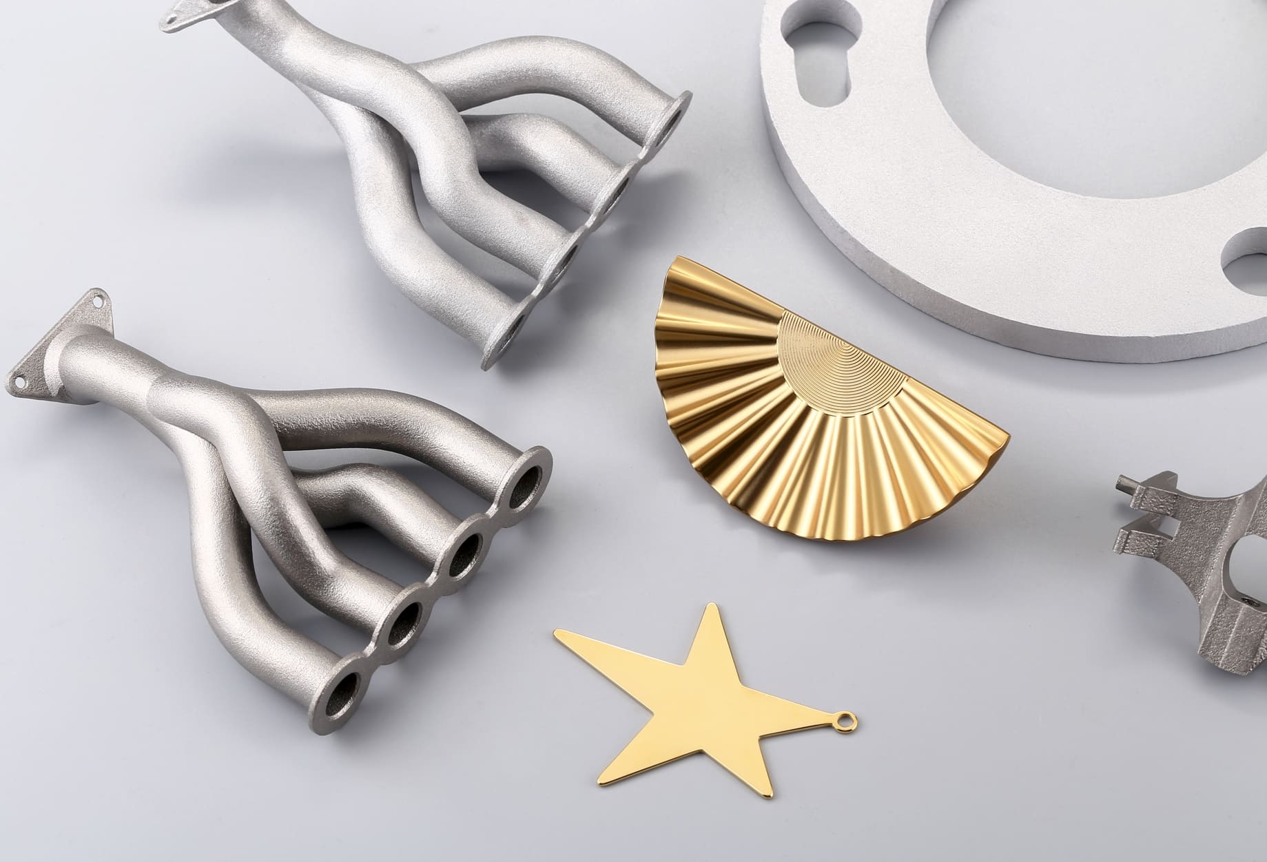
Image Source: Materialise
Build Orientation: Principles and Decision Criteria
Build orientation in SLM controls three linked outcomes, including the amount and location of support structures, the way heat flows through the part during processing, and the directionality of mechanical properties and surface finish. In practice, that means the best orientation is almost always a trade-off between mechanical performance, surface quality, support volume, and build time.
Key Objectives When Choosing an Orientation
• Protect critical surfaces. Prioritize how you expose precision faces, mating surfaces, or areas that will be CNC-finished.
• Manage thermal conduction paths. Orient so that heat can be drained to the baseplate or to large solid regions, which reduces local overheating and distortion. Tight control of powder-bed temperature and preheating also matters for distortion control.
• Minimize supports where possible. Supports add material, time, and post-processing effort and often leave scarring on contact zones.
• Balance build height vs. footprint. Vertical orientations reduce XY footprint but increase Z layers; flat orientations shorten Z but increase XY footprint and potential support area.
• Consider mechanical anisotropy. When tensile or fatigue loads are critical, align the load axis to print directions that offer better properties.
Practical Orientation Rules of Thumb
• If a hole or bore must be precise, orient it close to vertical for the best roundness.
• For long, thin features requiring tensile strength, orient the long axis vertically when strength in that direction is needed.
• Aim for local overhangs ≤ 45° where possible to reduce heavy supports; if geometry prevents it, move the part or add small design changes to create self-supporting surfaces.
• If a part must be free of visible support scars on a cosmetic face, orient that face away from support contact or plan for CNC finishing.
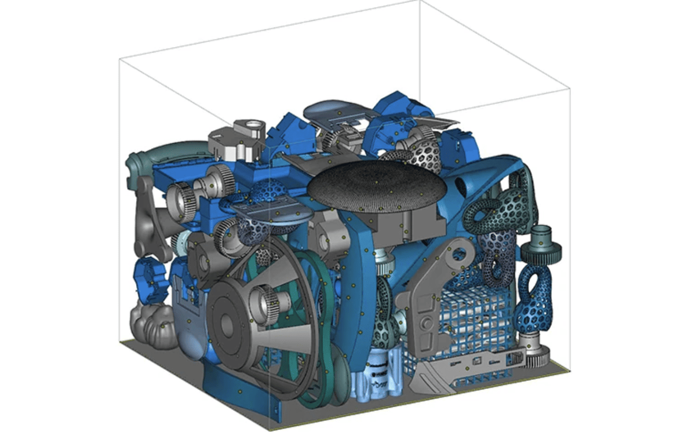
Nesting: Throughput and Thermal Interaction
Nesting (part packing) maximizes machine utilization and throughput while managing thermal interactions between parts on the build plate. Good nesting reduces cost-per-part and operator time; poor nesting raises the risk of cross-part thermal effects that can produce hotspots, higher residual stress, or localized failures. Automated nesting tools from vendors can dramatically shorten planning time while adhering to machine-specific constraints.
Packing Density vs Thermal Safety
Higher packing density increases throughput but can elevate local heat accumulation. Powder bed packing and local part distribution will change how heat flows across the plate; groups of dense, similar geometry parts can act as heat islands. For metal SLM, consider grouping similar geometries and materials and avoid mixing tiny and very large parts in the same cluster unless you’ve simulated the thermal outcome. Studies of packing and thermal conductivity show that packing density affects thermal behavior and must be balanced with risk.
Spacing Rules and Layout Practices
• Minimum horizontal gaps: follow machine vendor recommendations for inter-part spacing to avoid recoater collisions and ensure powder reflow; typical minimum gaps are machine-dependent.
• Stagger vs grid: Staggering small parts can reduce consecutive recoater impacts and distribute thermal load more evenly.
• Vertical stacking: only use with extreme caution; stacked parts change heat conduction to the plate and make failure containment harder.
• Symmetry & balance: distribute mass across the plate where possible to avoid asymmetric thermal stress patterns and warping.
Automation, Prioritization, and Build Planning
Use nesting software that is orientation-aware and able to tag parts by priority. For production runs, schedule builds with mixed volume across machines rather than cramming every part into a single high-risk dense nest. Vendors and software suites often offer multi-platform scheduling and automated nesting options to balance cost and reliability.
Support Strategy: Types, Placement and Removal
Supports perform three functions: provide mechanical anchoring during the build, conduct heat away from overhangs and thin features, and protect the recoater by keeping fragile geometry from interfering. Their design directly affects build reliability, part distortion, finish quality at contact points, and post-processing workload.
Common Support Types and When to Use Them
• Block/dense supports: provide robust thermal conduction and anchoring for heavy or highly stressed areas, use where distortion risk is high.
• Line/point supports: used for slender features or to minimize contact area; quicker to remove but may not conduct heat as effectively.
• Tree/branch supports: reduce contact points and post-removal scarring, useful for complex geometries, but they require sophisticated generation and validation algorithms. Research and practical methods for tree-like supports continue to improve removal and stress behavior.
Placement Strategy
• Primary anchors: place robust supports at structural load points where the part needs the most anchoring to the plate.
• Thermal (secondary) supports: create a web of thin conduction paths where heat would otherwise accumulate; don’t rely on aesthetic or sparse supports for thermal conduction.
• Protective rails: use sacrificial rails or cages in regions prone to recoater interference. These sacrificial structures are cheap insurance against catastrophic recoater knocks.
Balance Removability and Thermal Function
Dense supports help heat removal, but are painful to remove and leave more machining work. Tree/point supports reduce removal effort but may not sufficiently cool aggressive overhangs. A hybrid approach, dense supports at high-stress anchors and tapered/branching supports for overhangs often gives the best compromise.
Design for Easy Removal
• Add designed breakpoints or thin necks between the support and the part where possible.
• Where surface finish matters, move the contact zone to non-critical faces or add CNC allowances.
• Consider supporting locations that are accessible to automated removal fixtures or manual tools; hidden, enclosed contact zones are trouble.
Support Generation Tools and Simulation
Modern build preparation tools let you tune support density, contact foot geometry, taper, and topological placement. Always run a distortion/residual stress simulation on critical parts or a dense nests simulation, which often reveals interactions that manual inspection misses. Academic and vendor research continues to push more efficient truss and tree-type supports that reduce contact points while maintaining thermal conduction.
 0
0


COMMENTS
- Be the first to share your thoughts!