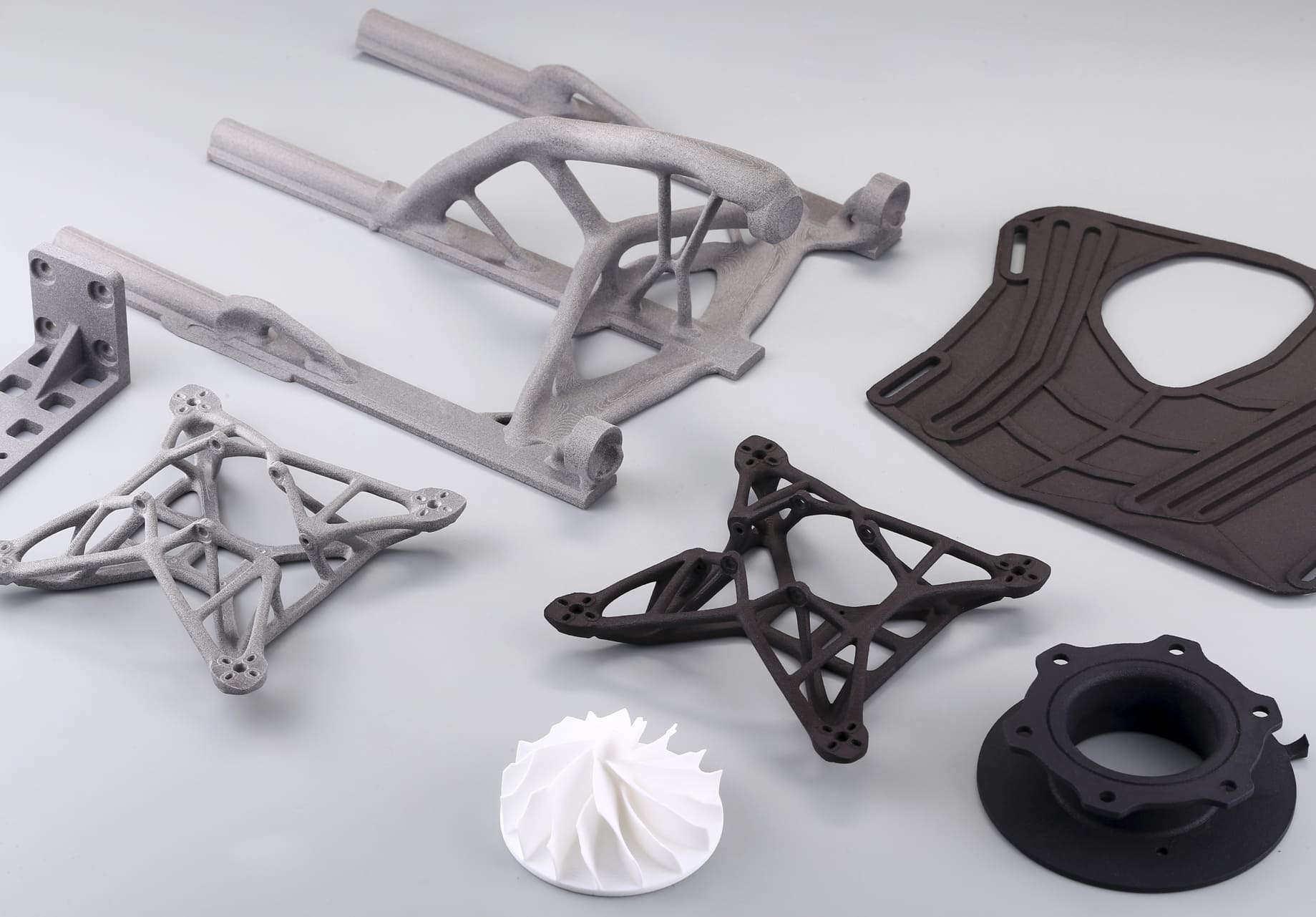
PA 11 (polyamide 11) is a bio-based nylon increasingly favored for functional parts that must take repeated loading. Its balance of ductility, toughness, and resistance to chemicals and abrasion makes it an attractive choice for components subject to cyclic stresses. To get the most fatigue resistance from PA 11, you must consider process, part design, and post-build treatments together.
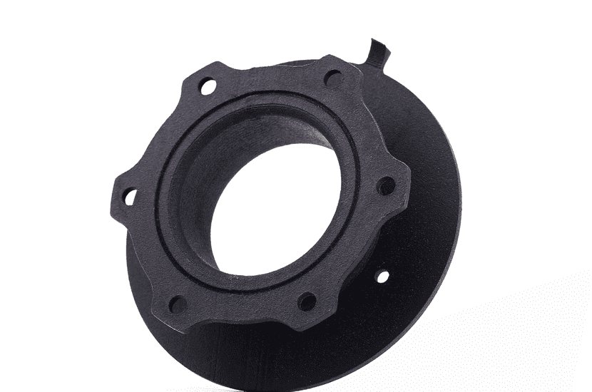
Image Copyright © 3DSPRO Limited. All rights reserved.
Why PA11 Behaves Well Under Cyclic Load
PA 11’s mechanical behavior under cyclic loading comes from a few linked material traits:
Ductility and energy dissipation. PA 11 exhibits relatively high elongation-at-break and a capacity to yield locally before brittle fracture. Under many cyclic loading regimes, that means loads are accommodated by local plasticity rather than a single sharp crack propagating rapidly.
Toughness and crack blunting. The material’s toughness helps blunt microcracks at their initiation sites. Rather than immediate catastrophic propagation, cracks may grow slowly, allowing design and process choices to dominate lifetime.
Moisture-dependent behavior. Like other nylons, PA 11 absorbs moisture, which plasticizes the polymer but can also change dimensional stability and long-term creep. In many service conditions, the plasticizing effect improves fatigue resistance, but environmental cycling can complicate predictions.
Crystalline/amorphous balance. PA 11’s semi-crystalline structure influences crack-initiation and propagation behavior. Processing that increases uniform crystallinity and reduces internal defects will generally improve fatigue performance.
In short, PA 11’s toughness and ductility reduce sensitivity to small defects, but fatigue life still depends strongly on defects, surface condition, and the details of loading.
SLS and MJF Influences on Fatigue
When using PA 11 in additive manufacturing, the process has an outsized effect on fatigue life because it determines porosity, interlayer bonding, surface roughness, and internal stress. Here are the primary process-driven variables to watch:
Part density and porosity. Voids act as crack-initiation sites. Both SLS and MJF can produce parts with microvoids if energy input, powder quality, or scan strategy are off. Maximizing fused density (without overheating) reduces initiation sites and extends life.
Neck formation between particles. The quality of fused necks between powder particles determines the microstructure that the crack must traverse. Well-fused necks raise fracture resistance.
Anisotropy and layer structure. Powder-bed parts are often anisotropic. Build direction and scan orientation change local strength and toughness. For cyclic load, align the principal stress direction with the direction that produces the best inter-particle bonding.
Thermal history and residual stress. How the bed is heated, the cooling rate, and localized re-scans create thermal gradients and residual stresses that can either help or hurt.
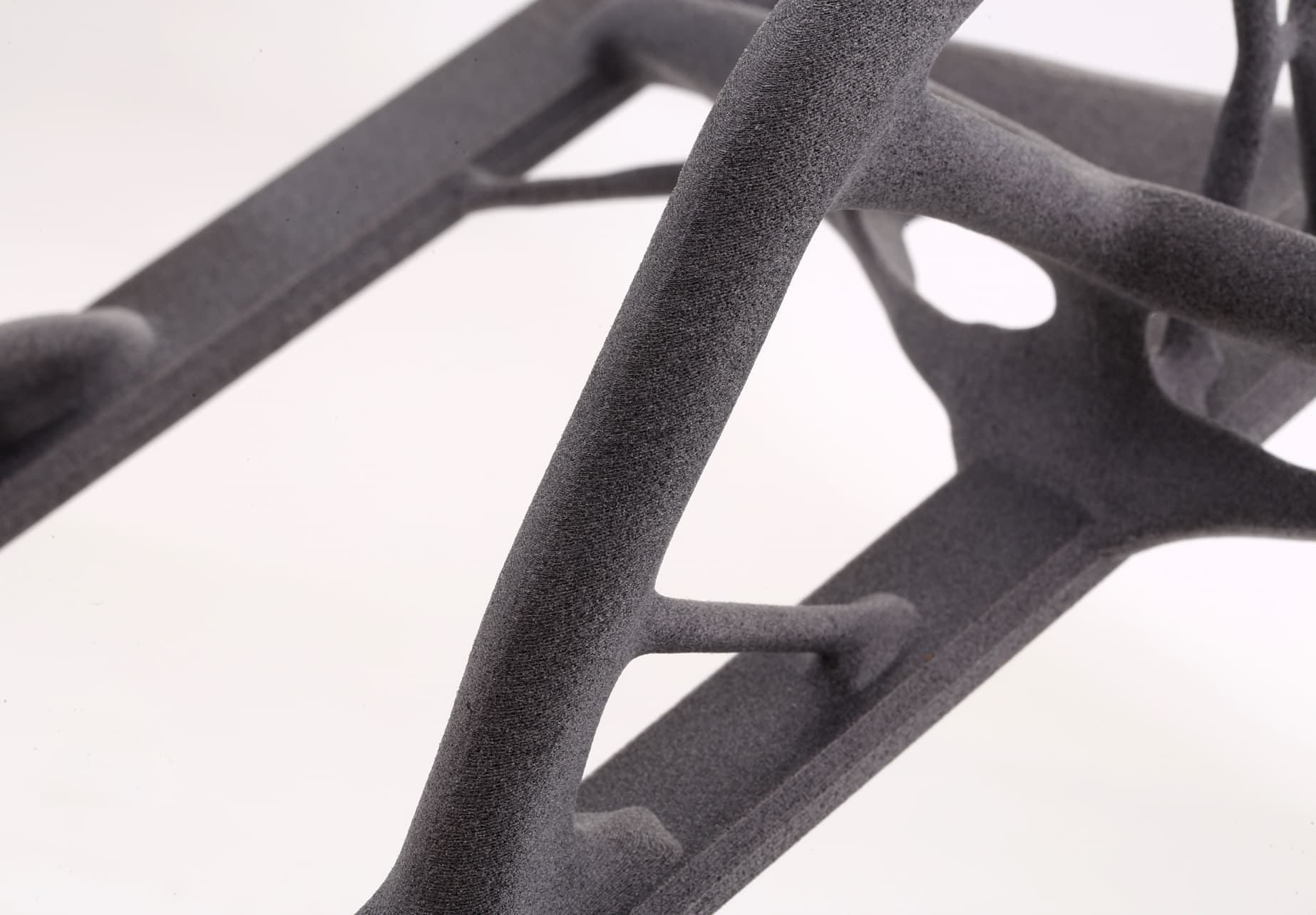
Surface condition. Rough surfaces amplify local stresses. Unfinished surfaces from SLS or MJF are common trigger points for fatigue cracks.
Process variants and parameters. Layer thickness, energy density, hatch spacing, and scan strategy all trade off surface quality, density, and throughput. Generally, prioritize parameters that increase density and reduce surface roughness when fatigue life is important.
Reinforcements and Material Variants
Short glass or carbon fiber-filled PA 11. These increase stiffness and strength and reduce creep, which may reduce cyclic deformation for some load cases. However, rigid fibers increase notch sensitivity: cracks can nucleate at fiber ends or at poor fiber–matrix interfaces and propagate faster. Filled grades often have lower fatigue crack growth resistance under high-cycle, low-stress conditions than neat PA 11.
Impact modifiers and rubber toughening. These can improve resistance to crack initiation by increasing local energy absorption, often beneficial for fatigue initiation but sometimes at the cost of reduced stiffness.
Nanofillers and specialty blends. Small additions can enhance certain properties but may complicate processing and anisotropy in 3D printing.
Hybrid approaches. Consider local reinforcement in high-stress areas rather than filling the whole part. Inserts reduce stress at fasteners or bearing surfaces without compromising bulk ductility.
Design Rules for Fatigue-Resistant PA11 Parts
Good geometry and CAD practices dramatically boost fatigue life, regardless of material:
1. Eliminate sharp transitions. Use generous fillets at section changes, avoid sharp internal corners around cutouts and holes, and soften transitions where stress concentrates.
2. Smooth load paths. Design to distribute loads over larger areas rather than producing local peaks. For example, use broader bearing surfaces and radiused supports rather than thin tabs.
3. Control wall thickness. Avoid very thin sections that create high local strain; avoid very abrupt thickness changes that cause stress risers.
4. Add radiused holes and countersinks. Holes are common initiation sites. Add edge radii, chamfers, or boss features to reduce local stress concentration.
5. Orient builds to align principal stresses. For AM parts, orient the build so that the strongest filament or fused neck direction carries the primary cyclic load. Where loads are multi-directional, consider designing geometry that reduces dependence on a single anisotropic axis.
6. Design for surface finish. Where possible, design to minimize post-build machining on highly stressed surfaces; if machining or local finishing is needed, ensure processes do not leave microcracks.
7. Avoid cantilevers or unsupported thin tabs. These are classic fatigue hotspots. If unavoidable, add ribs or change geometry to reduce bending stresses.
8. Use stress-relief features. Small relief grooves, rounded terminations of cutouts, and strategic stiffeners can slow crack initiation and propagation.
How to Extend Fatigue Life
Practical, proven steps to get more cycles from a PA 11 component:
Improve surface quality. Surface smoothing, targeted machining, or thin polymer coatings reduce microscale notches that start cracks.
Thermal stress relief. Controlled thermal treatments reduce residual tensile stresses from the build and can improve part homogeneity.
Sealing and infiltration. Infiltration with suitable resins or oils reduces open porosity and moisture ingress, lowering initiation chances.
Environmental control. If the service environment involves aggressive chemicals, UV, or temperature extremes, consider protective coatings, environmental barriers, or choose a PA 11 variant with stabilizers.
Local reinforcement and inserts. Use metal or polymer inserts in high-cycle contact areas to take the worst of the local stress and prevent surface damage to the PA 11.
Design for inspection and maintenance. Make critical areas accessible for visual inspections; plan scheduled replacements for known high-stress subcomponents rather than risking catastrophic failure.
Test and qualify with representative loading. Develop S-N data for your part geometry, build orientation, and post-process state. Include environmental conditioning in test plans so lab results reflect real service.
Apply conservative safety factors based on validated tests. For fatigue, small increases in stress can drastically reduce life; design margins are essential.
 0
0


COMMENTS
- Be the first to share your thoughts!