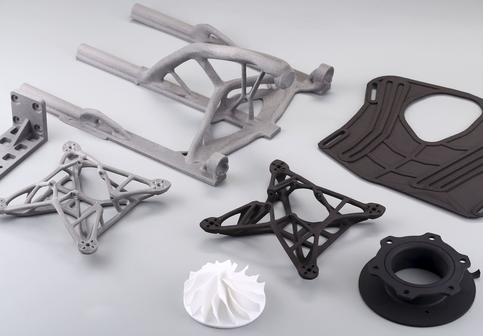
Thermoplastic polyurethane (TPU) powders used in selective laser sintering (SLS) let designers build truly flexible, resilient parts, such as gaskets, bellows, wearable straps, and compliant mechanisms. But TPU behaves very differently from rigid SLS nylons. Its elastomeric nature, thermal window, powder flow, and powder-reuse effects change how fine features, clearances, and hollow parts must be designed.
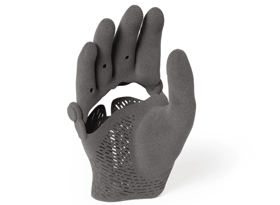
Image Source: Formlabs
Dimensional Rules and Minimums
Minimum Wall Thickness
For reliable flexible parts, target 1.0–1.5 mm as your default minimum wall thickness. Thinner walls (≈0.7–1.0 mm) can print on some systems but become very delicate and inconsistent; thicker walls (≥3 mm) make parts noticeably stiffer.
Minimum Feature Size
Raised or recessed details should be at least 0.7–1.5 mm in height/width for reliable visibility and durability on TPU SLS; very fine engraving often disappears or fills in.
Clearances for Moving Parts
Use 0.5–0.8 mm clearance for many SLS TPU moving interfaces as a baseline; for tighter designs, you will need test prints. Some vendors recommend 0.6 mm as a safe minimum to avoid fusing for mechanical linkages.
Minimum Hole Sizes
If you create closed cavities, include at least two drain/escape holes; a commonly recommended diameter is ≥3.5 mm so unsintered powder can be reliably removed. Smaller holes often trap powder and make parts heavy and incompletely cleaned.
Geometric Considerations Unique to TPU
TPU’s flexibility and low elastic modulus change how the geometry behaves after sintering.
Avoid Abrupt Section Changes
Sudden jumps from thin to thick increase localized cooling differences and stress concentrations, which can distort flexible parts or create hard/soft interfaces. Use fillets and tapered transitions.
Hollow Parts and Powder Removal
Hollowing saves material but must be planned: place drain holes at low points, add multiple holes, and avoid internal trapped pockets or very thin interior walls. Use internal ribs to control wall deflection without making sections so thick.
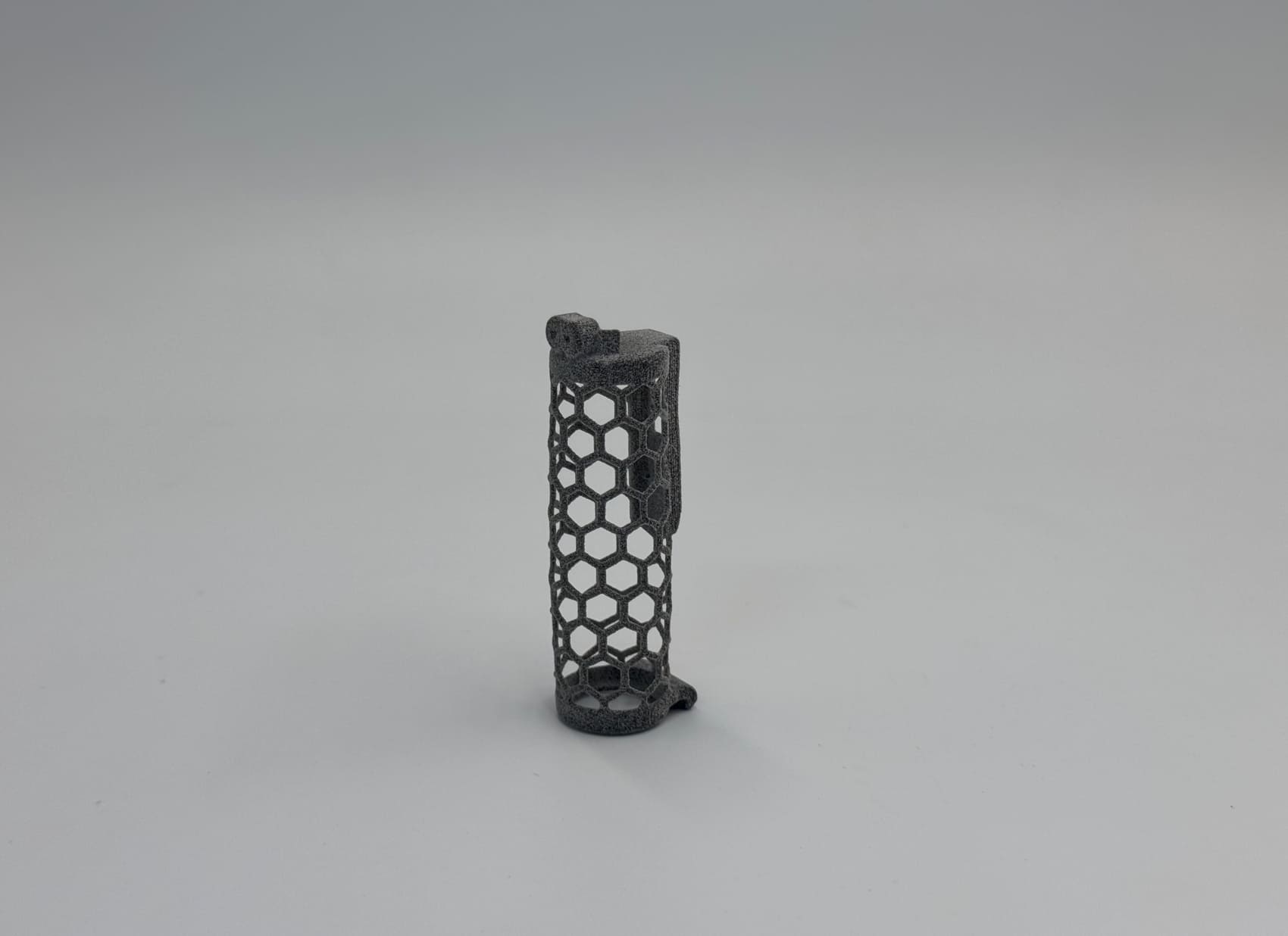
Lattices and Compliant Designs
TPU works well for lattices and compliant mechanisms, but cell size and strut thickness must respect the minimum feature rules. Very thin struts below the recommended wall and feature sizes will be brittle or inconsistent. Prototype lattice samples at the intended cell size to validate stiffness and fatigue behavior.
Moving Parts, Hinges, Snap-Fits and Living Hinges
SLS allows printing assemblies in one build, including hinges and interlocking parts, but TPU’s elasticity means design choices differ.
Clearance and Movement
Use at least 0.5–0.8 mm clearance for free movement of assembled parts as a starting point. Clearances that work for rigid PA12 often fuse or behave differently in TPU because parts deform during and after sintering.
Integral Hinges and Living Hinges
For living hinges in TPU SLS, design hinge areas with gradual thickness, and consider adding supporting radii to spread strain. TPU can handle many cycles, but hinge fatigue life depends on local strain amplitude.
Snap-Fits
Design flexible snap geometry with rounded corners, larger engagement radii, and more generous tolerances than rigid materials. Since TPU relaxes under load, avoid extremely high initial stresses in the snap, design for moderate deflection during engagement and provide sufficient contact area to resist creep over the product lifetime. Prototype to tune retention and fatigue.
Shrinkage and Compensation
SLS parts shrink slightly as powder sinters and cools. For TPU powders, you should expect and plan for 1–4% linear shrinkage depending on material grade, machine, and process parameters; many TPU powders measure around ~3% shrinkage on standard test coupons.
Tolerances
TPU SLS tolerances are typically looser than rigid nylons because elasticity increases dimensional spread and measurement ambiguity.
Typical Expectations
For many SLS TPU parts, expect dimensional accuracy on the order of ±0.2–0.5 mm for moderate features; fine details and thin flexible walls will vary more. For assemblies, accumulate tolerances across mating surfaces and design with generous allowances or use post-process machining/finishing for critical fits.
Orientation Effects
Build orientation affects perceived stiffness and measured dimensions. Parts printed with load-critical features aligned with the layer plane can behave differently from those printed across layers.
Measurement Guidance
When measuring flexible parts, use controlled fixturing or a compressive fixture to avoid dimensional errors caused by hand pressure.
Surface Texture and Post-Processing
TPU SLS parts have a slightly grainy, matte texture from powder particles. On flexible parts, the texture is apparent and can affect sealing or skin comfort.
Finish Options
Common post-processes include light bead-blasting, dyeing or impregnation for color and smoother finish, and coatings or sealing for improved abrasion resistance or airtightness. Bead-blasting is effective, but use conservative settings for thin-walled TPU.
Effect on Mechanicals
Any surface removal will reduce thickness and can affect fatigue life. Avoid aggressive post-processing on hinge regions or thin walls.
 0
0


COMMENTS
- Be the first to share your thoughts!