Residual stress is one of the defining challenges in metal 3D printing. Left unmanaged, it causes distortion, cracks, reduced fatigue life, and parts that simply won’t meet tolerance.
What Causes Residual Stress in Metal 3D Printing
Rapid Localized Heating and Cooling
Powder-bed and directed-energy processes melt tiny volumes quickly. As material melts and re-solidifies, steep temperature gradients form between the hot melt zone and cooler neighboring material. These gradients create non-uniform thermal expansion and contraction; when constrained by the surrounding solid material, the result is locked-in stresses.
Layered Deposition and Constraint
Each new layer is welded to previously solidified material. If the new layer cools and wants to shrink but is constrained by lower layers or supports, tensile stresses build. Over many layers, these add up and can cause out-of-plane warp or cracking.
Phase Transformations and Microstructure Changes
Some alloys undergo phase changes on cooling, such as martensitic transformations in steels, that involve volumetric change and can introduce or amplify stresses. Heat-affected microstructure gradients through the part thickness also produce mismatch strains.
Geometry and Boundary Conditions
Sharp section changes, thin-to-thick transitions, long cantilevers, and unsupported overhangs concentrate stresses. Build orientation and support placement impose mechanical constraints that change how stress accumulates.
Process Parameters and Scanning Strategy
Laser power, scan speed, hatch spacing, vector length, and pathing patterns control heat input and distribution. Certain scan strategies lead to hot spots or elongated temperature gradients and, therefore, higher residual stress.
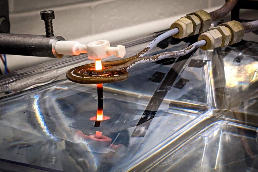
Image Source: MIT
How We Measure Residual Stress
1. Destructive Methods
• Contour method: cut the part and measure the deformation of the cut surfaces to reconstruct the original stress field. Gives high fidelity full-field maps but destroys the part.
• Hole-drilling and incremental slitting: remove material locally and measure strain relaxation with strain gauges. Semi-destructive and useful for spot checks.
2. Non-Destructive Diffraction Techniques
• X-ray diffraction (XRD): measures lattice spacing changes due to elastic strain at and near the surface.
• Neutron diffraction: penetrates deeply and can measure subsurface stresses in thick sections, but requires specialized facilities.
These diffraction methods are quantitative but limited by access, sample geometry, and resolution constraints.
3. Ultrasonic and Acoustic Methods
Ultrasonic wave speeds and acoustoelastic measurements can infer stress states non-destructively in some cases; practical for larger structures and in-process proxies.
4. In-Process and Indirect Monitoring
Melt-pool thermography, pyrometry, and high-speed imaging don’t measure stress directly but provide thermal histories that correlate strongly with stress buildup. Combined with models, they permit process control to reduce stress formation.
Design Strategies to Reduce Residual Stress
• Build orientation. Orient parts to minimize unsupported overhangs and long cantilevers; orient critical features so they are near the baseplate when possible. Shorter unsupported spans reduce bending moments during cooling.
• Geometry smoothing and fillets. Replace abrupt section changes with tapered transitions and fillets to avoid geometric stress concentrators. Thick-to-thin transitions should be eased where function allows.
• Uniform wall thickness. Where possible, keep wall thicknesses uniform or use stepped transitions. Thin-thick changes create large thermal gradients.
• Split and assemble. For very large or thin features, design the part as assemblies of smaller components that are joined after stress relief. It avoids printing a single long structure that warps.
• Support strategy as a thermal and mechanical path. Design supports not only holding geometry but also conducting heat away and stabilizing high-stress areas. Thermal bridges help reduce local gradients.
• Topology and lattice placement. Use lattices to reduce mass while avoiding long unsupported spans. Place lattices or ribs as thermal buffers to smooth gradients.
• Tolerance and machining stock. Leave extra material for post-machining. That gives tolerance for distortion and allows removal of stressed surfaces.
• Select process and material mindful of stress behavior. Processes with preheating or lower cooling rates tend to produce less severe residual stresses for comparable geometries. Some alloys are also less prone to transformation-induced stress.
Post-Build Thermal and Mechanical Stress Relief Methods
Stress-Relief Annealing
Controlled heating to an intermediate temperature is held to allow creep relaxation, followed by controlled cooling. It’s the most common, economical first step to reduce locked-in stresses.
Hot Isostatic Pressing (HIP)
HIP simultaneously applies high temperature and isostatic pressure to close internal porosity and reduce internal stresses. It can dramatically improve fatigue life as well as relieve some residual stresses, though final machining may still be necessary.
Solution + Aging or Tailored Tempering
For precipitation-hardened alloys, full heat treatment cycles are applied to achieve the desired microstructure and relieve transformation stresses.
Surface Mechanical Treatments
• Shot peening and shot blasting impart compressive surface stresses that significantly improve fatigue resistance.
• Laser shock peening (LSP) provides deeper compressive layers with less surface roughening and is especially promising for AM parts that need subsurface compressive stress profiles.
Vibration Stress Relief
Sometimes used for large components, the effectiveness is variable and typically lower than thermal methods, but it can be practical for small adjustments.
Common Issues and How to Fix
Problem: Part warpage after removal from the build plate.
Fixes: Improve support design and add thermal bridges; preheat substrate; change build orientation to reduce cantilevers; perform stress-relief anneal before final machining.
Problem: Cracking during the build (hot cracking or cold cracking).
Fixes: Modify alloy chemistry or choose a more crack-resistant material if possible; reduce peak thermal gradients, apply interlayer dwell, optimize scan strategy to avoid long continuous vectors.
Problem: Poor fatigue performance.
Fixes: Apply HIP to reduce internal porosity, then shot peen or LSP to introduce compressive surface stresses; ensure stress-relief and required heat treatments for the alloy.
Problem: Distortion in thin features or thin walls.
Fixes: Thicken sections where possible, add sacrificial ribs or support fins during build to stiffen geometry, or split the feature into multiple printed parts and join after anneal.
Problem: Surface tensile stress leading to early fatigue cracks.
Fixes: Remove tensile surface layers via machining or add compressive surface treatments, combined with an anneal cycle.
Problem: Inconsistent results between builds.
Fixes: Improve process control and monitoring; calibrate scan strategy; use simulation to identify sensitive parameters and add process windows; ensure consistent powder condition and preheat.
 0
0


COMMENTS
- Be the first to share your thoughts!