Thermal control is a core determinant of success in any 3D printed part. Large dimensions and high-temperature materials amplify the same physical problems, non-uniform temperatures, slow heat flow, and tight process windows, which produce warping, delamination, internal stress and dimensional drift.
How Heat Affects Large and High-Temp Prints
At a fundamental level, thermal trouble comes from two things, temperature gradients (different places at different temperatures) and rate of temperature change (how fast a region heats up or cools down).
Uneven cooling. Different cooling rates translate into different amounts of shrinkage. The result is warping, distortion, interlayer separation or internal tensile stresses that cause cracking later. The larger the part, the more likely some zones will lag thermally behind others.
Thermal mass slows equilibration. Thick sections and high mass make it harder for heat to distribute evenly. A large block will keep heat longer and can cause local overheating or prolonged cooling in nearby areas.
Tighter material windows. High-temperature polymers and engineering materials have higher glass transition and service temperatures. They require higher processing temperatures and often a more stable thermal environment; outside that, bond strength between layers or particles degrades.
Exotherms and phase changes. Some chemistries release heat during curing; others undergo phase changes (glass transition, sintering) that change mechanical behavior during heating and cooling. Those phenomena affect how and when stress develops.
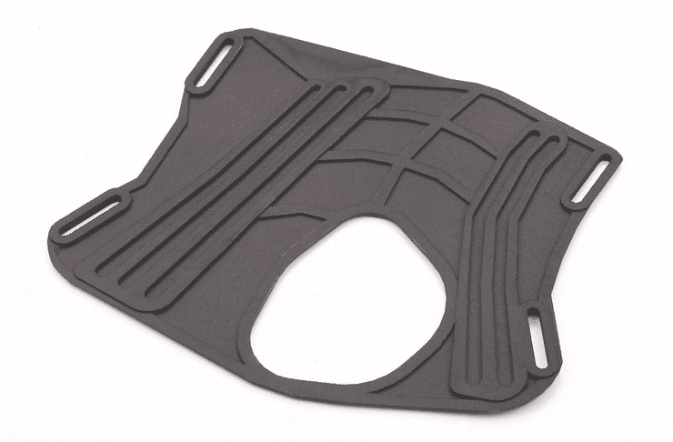
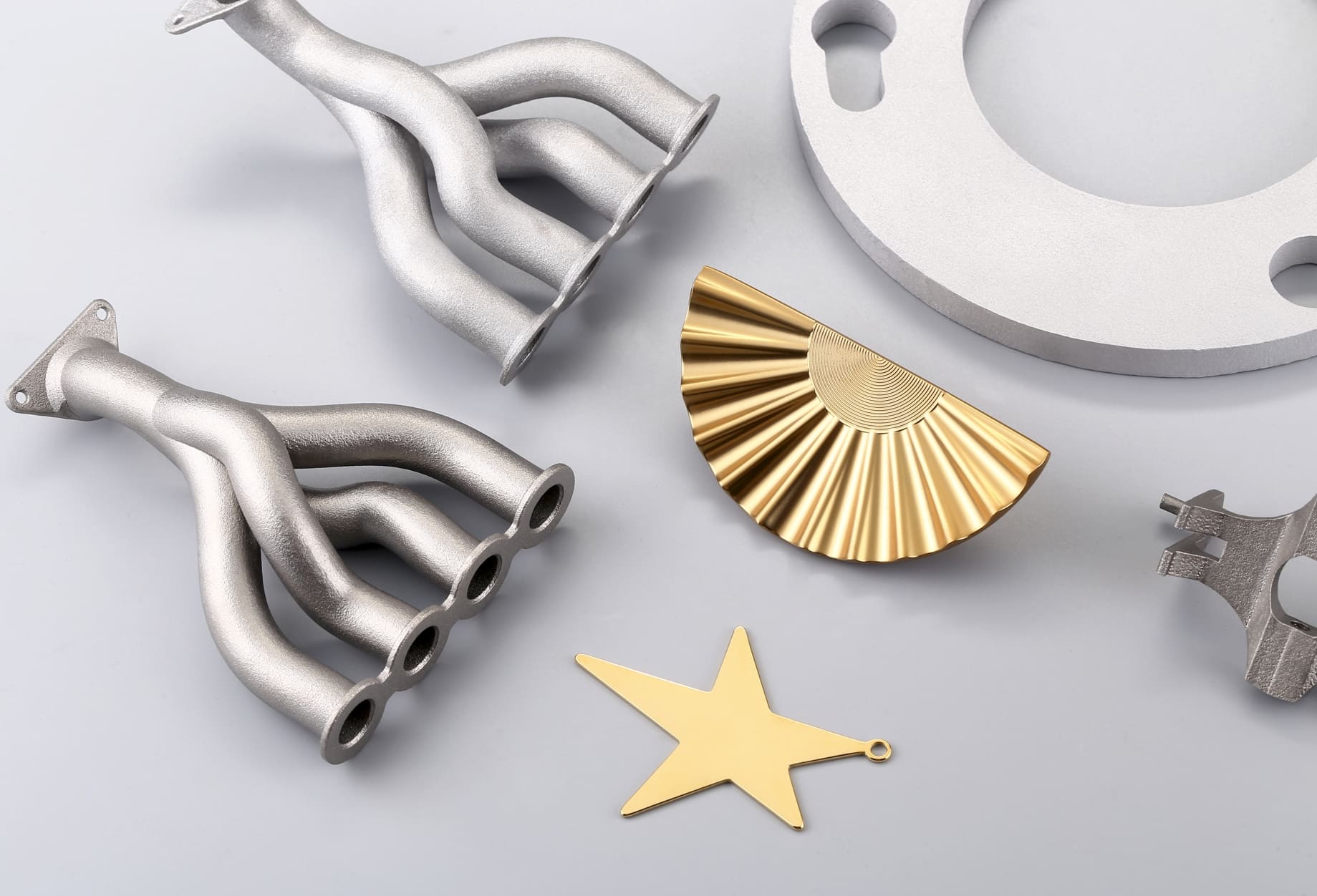
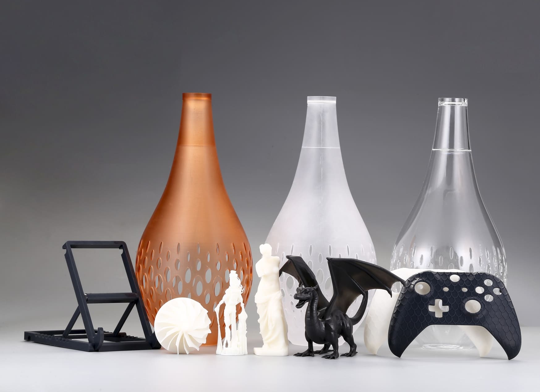
Image Copyright © 3DSPRO Limited. All rights reserved.
Principles of Thermal Management
1. Uniformity over peak temperature. A slightly lower but uniform environment often beats local hotspots and cold pockets. Gradients are the enemy.
2. Control ramp rates. Slow, staged heating and controlled cooling reduce thermal shock and let material relax. Avoid abrupt ventilation or sudden opening of the build environment.
3. Minimize heat sinks and hotspots. Insulate where heat is being lost; avoid concentrated local heating unless it’s carefully controlled and monitored.
4. Coordinate design, process and hardware. Geometry, scan/exposure strategy, and chamber/bed control interact. Treat them as a single system, changing one requires tuning the others.
5. Measure and close the loop. Use sensors (thermocouples, IR cameras, pyrometers) to validate that your intended thermal environment is actually being achieved, and use feedback control when possible.
6. Plan for post-process thermal steps. Annealing, stress relief and controlled cool-downs can be used intentionally to relieve residual stress, if done with proper profiles.
Design for Thermal Stability
1. Smooth transitions in cross-section. Avoid sudden thickness jumps. Fillets, chamfers and gradual tapers reduce local stress concentrations and heat-sink effects.
2. Balance mass and symmetry. Distribute large masses more symmetrically to avoid twisting during cooling. Place critical features away from abrupt thermal transitions.
3. Modularize where practical. Breaking a huge part into indexed segments lowers mass per printed section and makes thermal control simpler. Design reliable joints for post-assembly.
4. Use sacrificial features strategically. Brims, rafts, stiffeners or temporary ribs improve stability during thermal cycles and are removed in finishing.
5. Orient for thermal behavior. Consider how orientation affects heat flow and where most heat accumulates; orient to minimize large, uninterrupted surfaces forming perpendicular to cooling paths.
3D Printing Process Strategies
1. Enclose and insulate. Enclosures reduce drafts and slow unwanted cooling. Insulation on build plates, covers, or chamber walls increases uniformity.
2. Active temperature management with feedback. Where possible, use sensors placed in representative locations and simple closed-loop control to avoid overshoot and drift.
3. Moderate energy input and distribute it. Avoid concentrating energy in small regions repeatedly. Spread exposure, hatch direction, or toolpaths to distribute heat deposition more evenly.
4. Manage layer timing and dwell. Too-fast sequencing can leave adjacent areas underheated; intentionally lengthen dwell or slow down when printing large contiguous areas so heat has time to penetrate and layers bond.
5. Limit forced cooling during critical stages. Fans and rapid cooling are often useful for small features but can be harmful during large or high-temp builds. Use selective or delayed cooling strategies.
6. Implement staged cycles. For long thermal processes, break the cycle into ramp-up, hold, and controlled cooldown phases. This prevents thermal shock and gives time for relaxation.
7. Use test artifacts and thermal mapping. Before committing to a long, expensive build, run calibration prints and map temperature distribution with thermometers or an IR camera. Adjust strategy based on data.
8. Plan for material conditioning. Dry hygroscopic materials, degas resins, and precondition powders if the material chemistry requires it—material state affects how heat is absorbed and released.
Material Recommendations
1. Know the material’s thermal behavior. Glass-transition, melting or sintering ranges, thermal conductivity and CTE tell you how aggressively a material will react to gradients.
2. Treat hygroscopic materials carefully. Moisture changes thermal diffusion and bonding; drying and controlled storage improve thermal consistency.
3. Expect different relaxation times. Materials with higher Tg or crystalline phases often require longer holds or anneals to relieve stresses, plan for larger thermal cycles.
4. Anticipate exotherms and reaction heat. Some chemistries generate heat during cure, either reduce localized exposure or stage curing to avoid runaway local temperatures.
5. Plan post-processing. If you will anneal or sinter parts after build, design for the dimensional changes that will occur and use controlled furnaces/ovens with slow ramps.
 0
0


COMMENTS
- Be the first to share your thoughts!