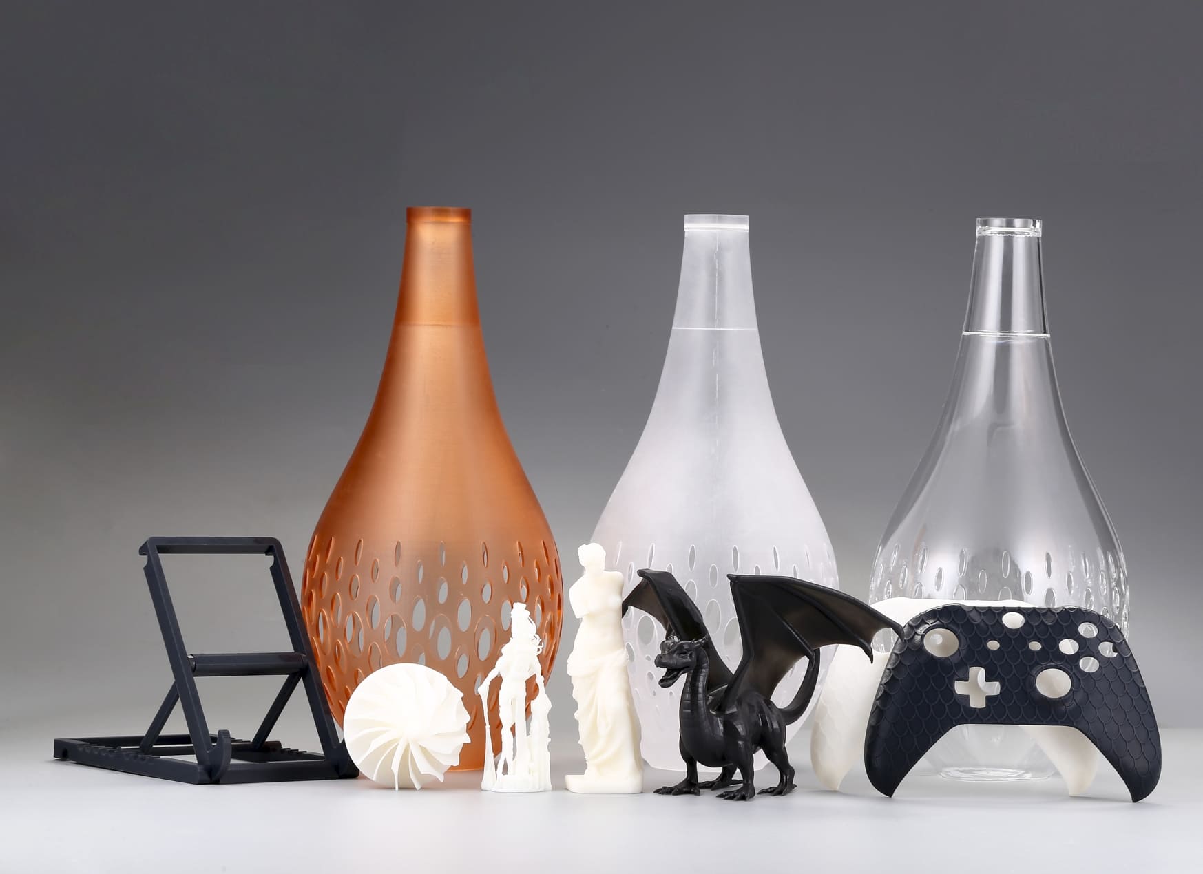
Designing for additive manufacturing requires a balance between aesthetics, function, and printability.
Core Principles of 3D Printable Design
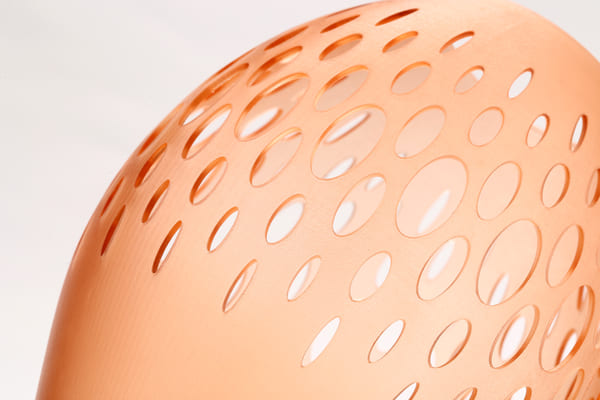
Wall Thickness and Feature Size
Maintaining the right wall thickness ensures structural integrity without wasting material. Minimum walls too thin lead to fragile parts, while overly thick walls increase print time and may warp.
Aim for 0.8–1.0 mm minimum walls on most systems, and scale up to 2–3 mm for load-bearing sections.
Overhangs, Bridges, and Supports
Excessive overhangs can sag or collapse mid-print. Limiting overhang angles to 45° or less often eliminates the need for supports.
For bridges, keep unsupported spans under 10 mm and add small sacrificial ribs to strengthen longer gaps.
Tolerances and Clearances
Clearances dictate how well parts fit or move together. Too tight, and pieces fuse; too loose, and assemblies wobble.
Standard interlocking clearance: 0.2–0.3 mm for SLA/SLS; 0.5 mm for FDM. Always test-print a fitting fixture before final production.
Part Orientation and Printability
Orientation affects surface finish, build time, and strength direction. Printing long axes vertically maximizes strength but raises print height and support needs.
Experiment with tilts of 30–45° to balance overhangs and layer lines while reducing support volume.
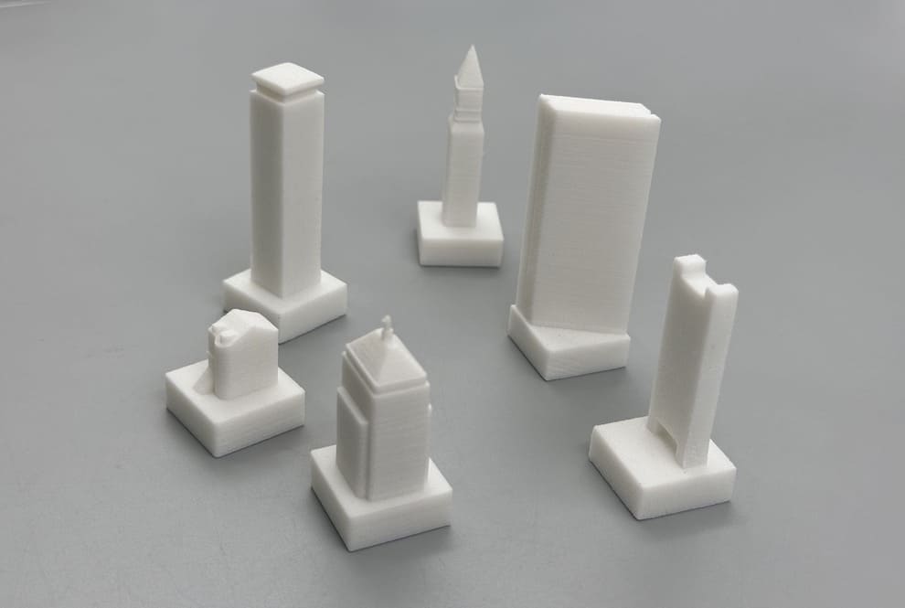
Image Copyright © 3DSPRO. All rights reserved.
Technology-Specific Guidelines for SLA, SLS, MJF, and SLM
|
Technology |
Min Feature Size |
Min Wall Thickness |
Typical Surface Finish |
Shrinkage Allowance |
|
SLA |
0.3 mm |
0.8 mm |
Very smooth |
1–2% |
|
SLS |
0.5 mm |
0.6 mm |
Gritty/matte |
1–3% |
|
MJF |
0.8 mm |
0.8 mm |
Fine matte |
1–2% |
|
SLM |
0.5 mm |
1.0 mm |
Metallic sheen |
2–4% |
Stereolithography (SLA)
Process: UV laser cures a liquid photopolymer, layer by layer.
|
Aspect |
Recommendation |
|
Min. Feature Size |
0.1–0.2 mm for simple features; ≥ 0.3 mm for text/ribs |
|
Min. Wall Thickness |
0.5 mm (general); ≥ 0.8 mm for unsupported walls |
|
Tolerances |
± 0.2 mm |
|
Orientation |
Tilt 30–45° to reduce peel forces; avoid large flat bottoms |
|
Supports |
Use fine “tree” supports; attach on non-critical areas; minimize contact tips |
|
Overhangs |
≤ 45° from vertical without supports |
|
Post‐Processing |
Rinse in isopropyl alcohol (IPA), UV cure; consider light sanding and primer for paint |
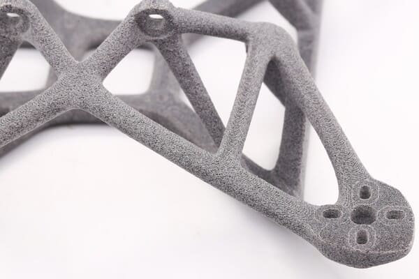
Selective Laser Sintering (SLS)
Process: Laser fuses nylon (or other) powder; unfused powder acts as support.
|
Aspect |
Recommendation |
|
Min. Feature Size |
0.7–1.0 mm for pillars and channels; ≥ 1.5 mm for holes |
|
Min. Wall Thickness |
1.0–1.2 mm (general); ≥ 2.0 mm for high-load walls |
|
Tolerances |
± 0.3–0.5 mm |
|
Orientation |
Build flat on Z-axis if stiffness is key; powder support relieves most overhang concerns |
|
Supports |
None needed internally; ensure adequate powder escape for enclosed voids (drain holes ≥ 2 mm) |
|
Overhangs |
Up to 90°; self-supporting in powder |
|
Post‐Processing |
Shot‐blast or bead-blast to remove powder; optional dyeing or tumbling for surface smoothness |
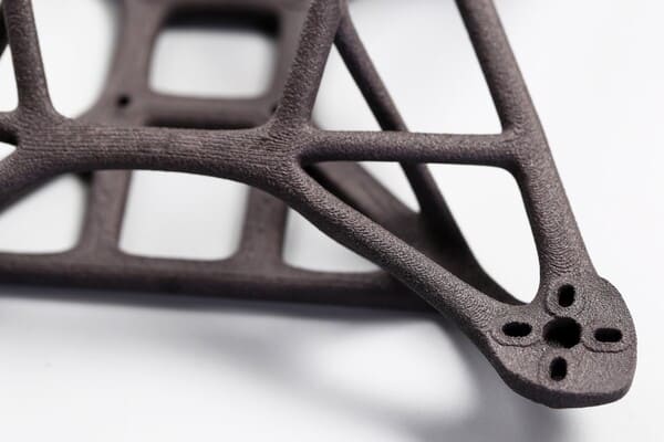
Multi Jet Fusion (MJF)
Process: Ink-jet fusing agents selectively bind powder, then IR lamps fuse layers.
|
Aspect |
Recommendation |
|
Min. Feature Size |
0.5–0.7 mm for simple geometries; ≥ 1.0 mm for fine details |
|
Min. Wall Thickness |
0.8–1.0 mm (general); ≥ 1.5 mm when high stiffness required |
|
Tolerances |
± 0.3 mm |
|
Orientation |
Many orientations work; align high-tolerance features in X–Y plane |
|
Supports |
None needed; avoid trapped powder in voids (drain holes ≥ 2 mm) |
|
Overhangs |
Up to 90°; powder provides support |
|
Post-Processing |
Similar to SLS: bead-blasting, dyeing; consider infiltration (e.g., wax) for strength and surface seal |
Selective Laser Melting (SLM)
Process: High-power laser fully melts metal powder (e.g., stainless steel, titanium).
|
Aspect |
Recommendation |
|
Min. Feature Size |
0.3–0.5 mm for simple metal features; ≥ 1.0 mm for through-holes |
|
Min. Wall Thickness |
0.8–1.0 mm (general); ≥ 1.5 mm for load-bearing thin walls |
|
Tolerances |
± 0.3 mm |
|
Orientation |
Orient to minimize unsupported overhangs; 45° build angle reduces warping |
|
Supports |
Mandatory for overhangs > 45°; attach supports under every overhang; plan for easy removal and grinding |
|
Overhangs |
≤ 45° without supports; avoid > 60° even with supports to reduce heat build-up |
|
Residual Stress |
Use hatching patterns and island scanning strategies; consider pre-heat bed |
|
Post-Processing |
Remove supports, stress-relieve (thermal treatment), CNC finish critical surfaces, shot-peen or bead-blast for surface finish |
Common Design Mistakes and How to Fix Them
Thin Walls Causing Breakage
Problem: Walls below the recommended thickness fracture under load.
Fix: Increase to technology’s minimum and reinforce with ribs.
Unsupported Overhangs Leading to Sagging
Problem: Overhangs past 45° droop or fuse.
Fix: Reorient model or add chamfers and sacrificial supports.
Excessive Supports Increasing Post-Processing
Problem: Too many supports waste material and time.
Fix: Rotate parts, introduce self-supporting angles, or split into subassemblies.
Misaligned Clearances Causing Assembly Issues
Problem: Snap fits too tight or loose.
Fix: Prototype test blocks, adjust clearance by ±0.1 mm per iteration.
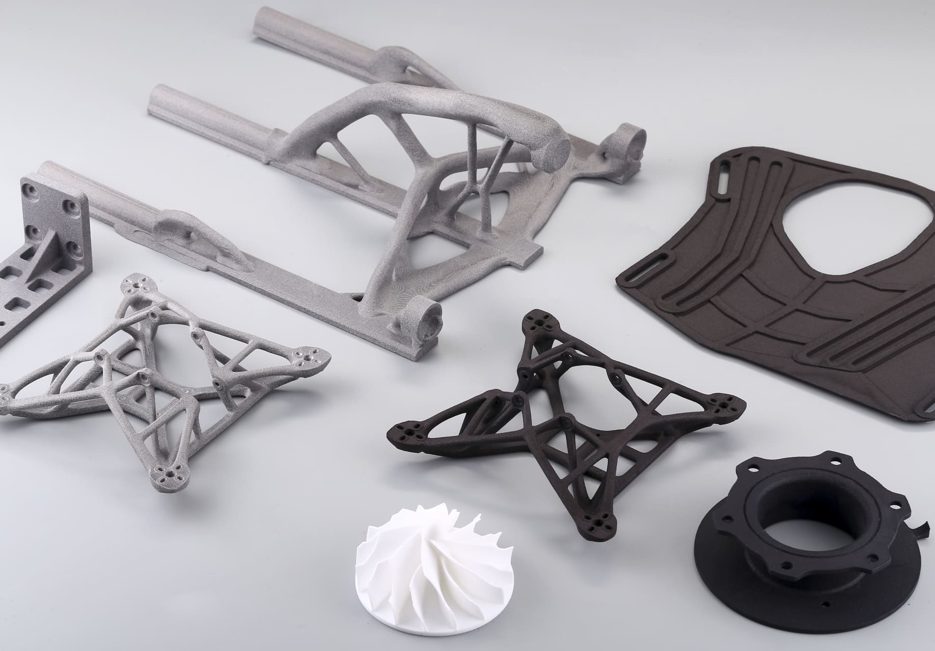
Advanced Design Strategies
Lightweighting with Lattices and Gyroids
Replace solid infill with parametric lattices to slash weight while preserving rigidity. Tools like nTopology and Rhino’s Grasshopper let you tailor cell size, wall thickness, and density regionally.
Embedding Functional Elements
Integrate threads, living hinges, and snap fits directly in your CAD. Use helical inserts for metal threads and design living hinges with compliant beam geometries to ensure long-term durability.
Topology Optimization and Generative Design
Leverage simulation-driven tools to identify stress paths and remove redundant material. Export optimized meshes, smooth critical surfaces in CAD, and add print-friendly features like chamfers and drainage holes.
DfAM Services at 3DSPRO
3DSPRO’s Design for Additive Manufacturing services streamline your path from concept to printed part:
1. Part review and feasibility analysis
2. Custom redesign for cost, strength, and print speed
3. Simulation of thermal distortion and support removal
4. Prototype iteration and material testing
5. Consulting on build orientation, nesting, and batching
Partner with 3DSPRO to unlock faster development cycles, optimized costs, and superior print success across SLA, SLS, MJF, and SLM platforms.
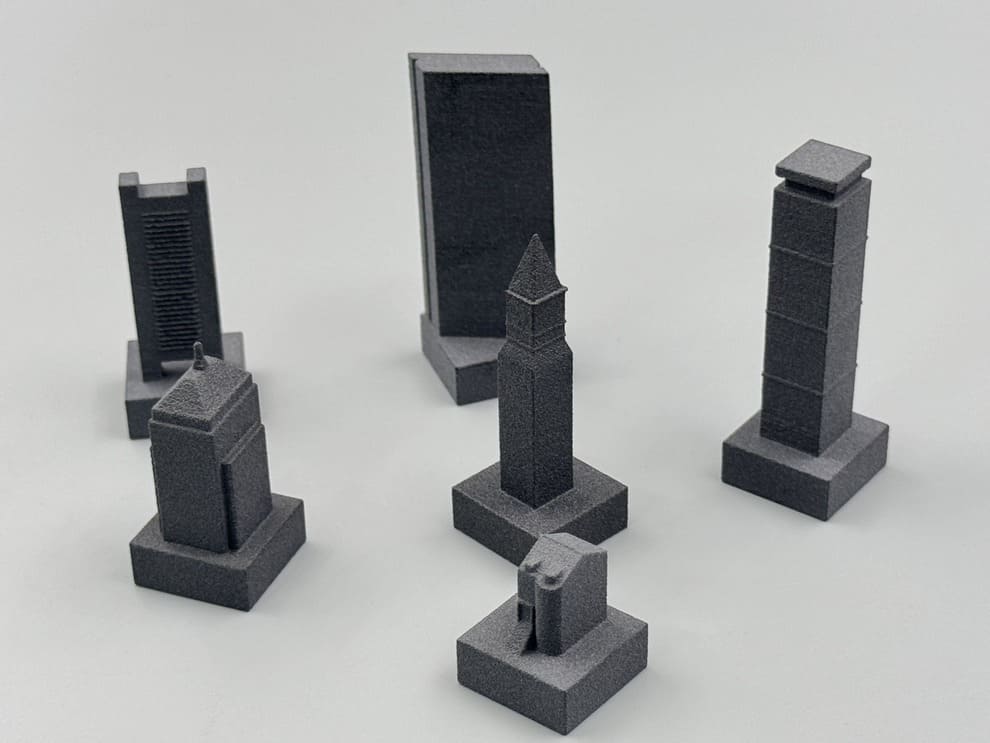
Image Copyright © 3DSPRO. All rights reserved.
 4
4


COMMENTS
- Be the first to share your thoughts!