Ceramic coatings are a powerful post-processing option when you need parts that withstand heat, abrasion, chemical exposure, or require electrical insulation. Unlike simply painting a part for looks, ceramic coatings can provide thin, hard, thermally stable layers that dramatically change a printed part’s performance without redesigning the core geometry.
What is A Ceramic Coating?
Ceramic coating covers a range of surface treatments that deposit ceramic material (or ceramic-filled binders) onto a substrate. There are two broad categories.
Low-Temperature, Binder-Based Ceramic Coatings
They are sprays, paints, or sol-gel solutions that contain ceramic particles dispersed in a polymer or inorganic binder. They are applied like paint (spray, dip, brush) and typically cure at room temperature or with a low heat bake. The resulting layer is largely a composite: ceramic particles bonded by a binder. These coatings improve hardness, abrasion resistance, thermal stability, and chemical resistance without requiring extreme temperatures.
High-Temperature Ceramic Layers / Thermal Spray
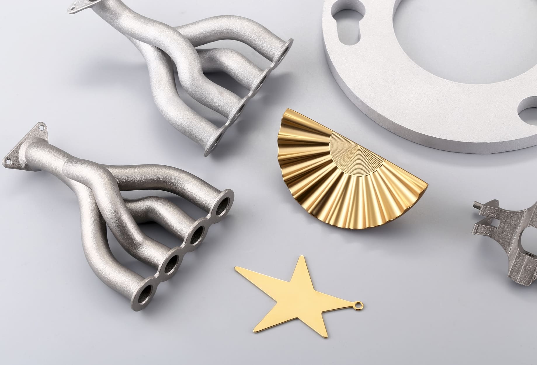
In industrial processes (plasma spray, HVOF, flame spray), molten or semi-molten ceramic is projected onto the part and rapidly forms a dense ceramic coating. These coatings can be much thicker and more purely ceramic (alumina, zirconia, etc.), and they deliver outstanding wear and heat resistance, but they require specialized equipment and sometimes pre- and post-processing.
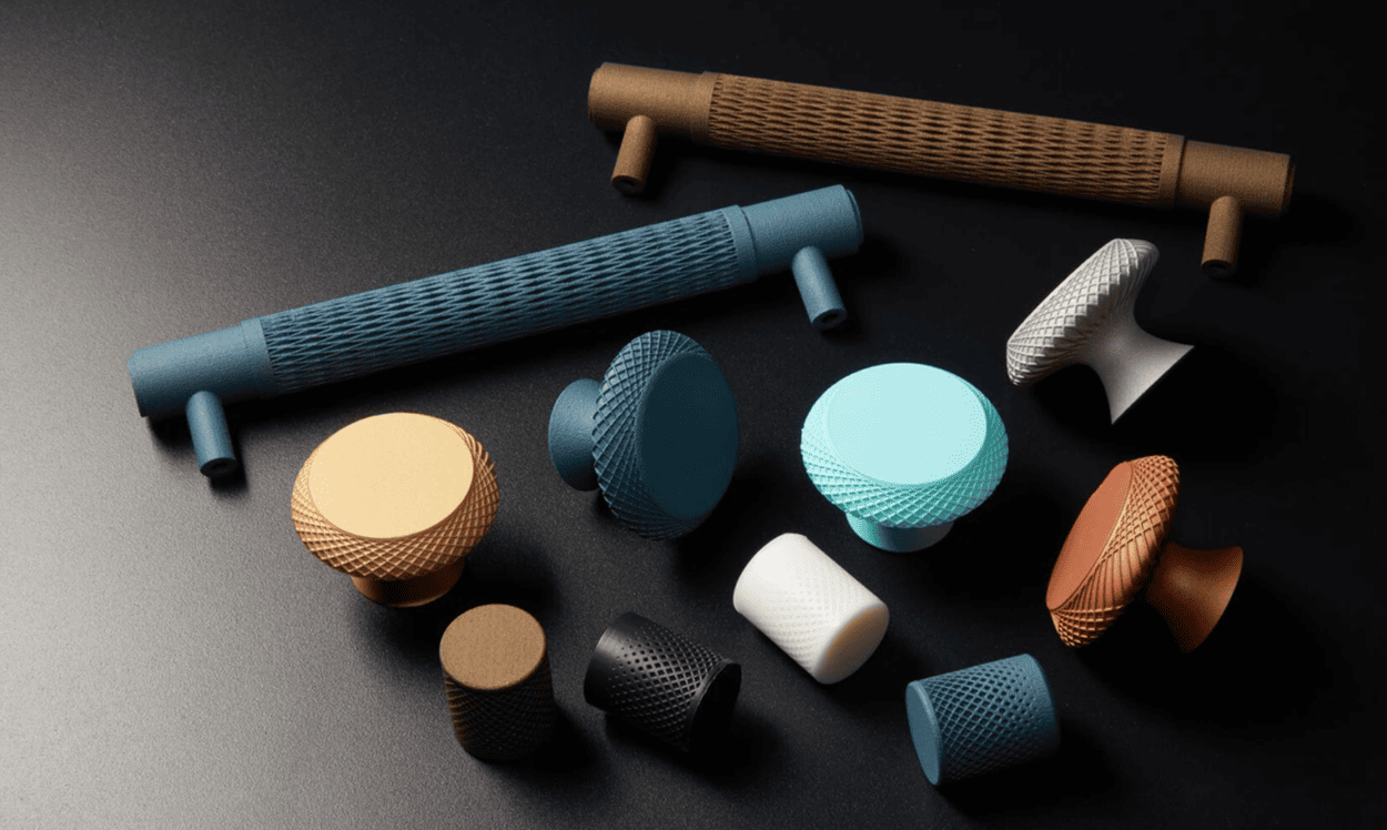
Image Source: Cerakote EU
Can 3D Printed Parts Use Ceramic Coating?
Yes. Most 3D printed parts can receive a ceramic coating, but success depends on:
• Substrate chemistry and surface energy: Rough, porous, or polar surfaces (like nylon) generally accept coatings better than very smooth, low-surface-energy materials (some SLA resins or fluorinated plastics).
• Temperature sensitivity: Many polymer prints cannot tolerate the high sintering or firing temperatures required to fully densify ceramic powders. Thermally stable polymers (PEEK, ULTEM/PEI) or metal prints are more compatible with high-temperature ceramic processing; for common FDM plastics, you’ll usually use low-temperature binder-based coatings or industrial thermal spray approaches that are applied without heating the substrate above its limit.
• Part geometry: Deep cavities, tight internal channels, or complex lattices can trap coating and create pinholes or uneven thickness.
• Adhesion strategy: Mechanical anchoring (roughening), primers, and chemical coupling agents (silane primers) greatly improve coating adhesion on polymers.
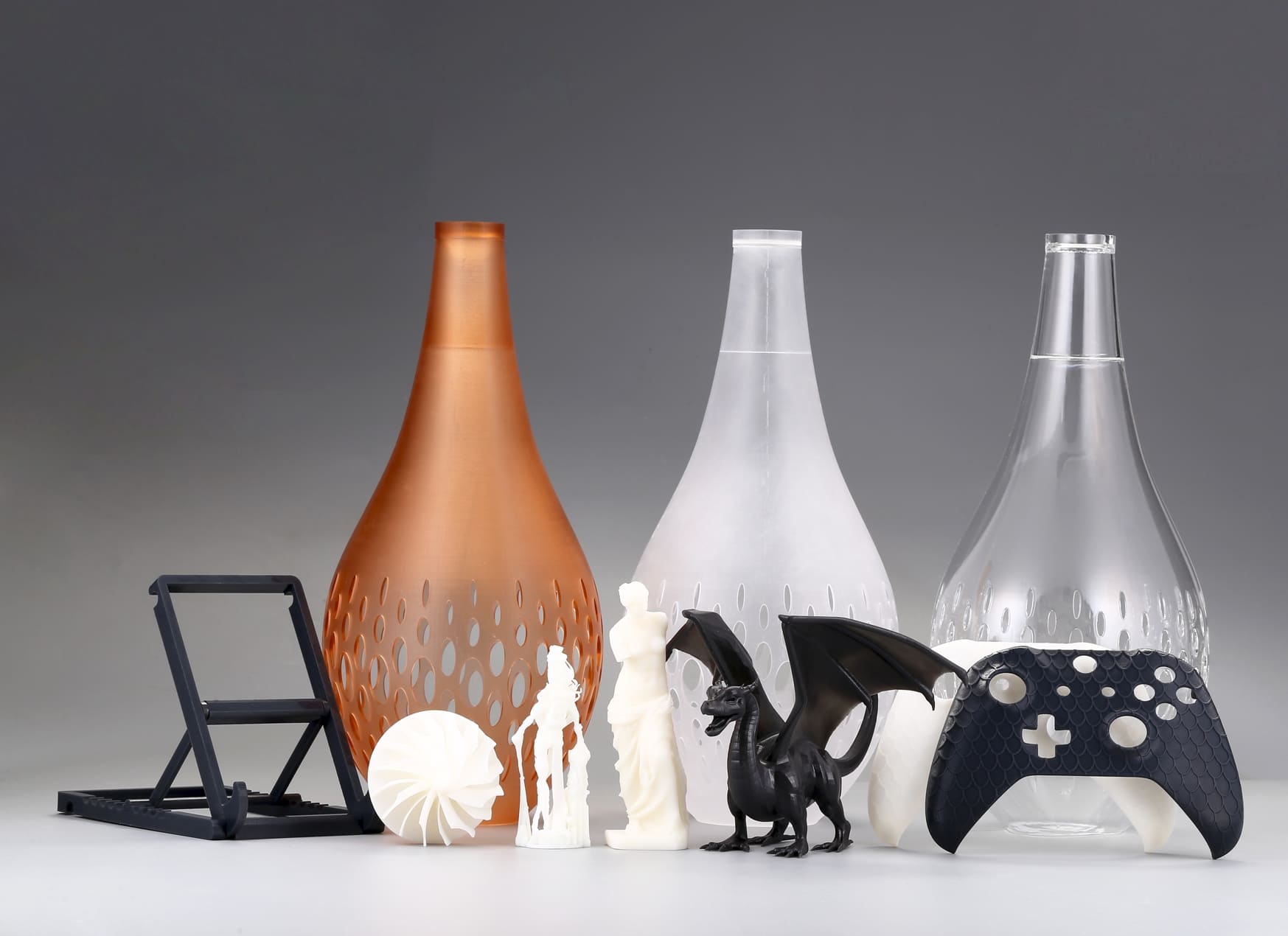
Which 3D Printed Materials Work Best
FDM Thermoplastics (PLA, ABS, PETG, Nylon)
They are good candidates for binder-based ceramic coatings applied at room temperature or low bake. Nylon and glass-filled nylons accept coatings particularly well due to surface roughness and polarity. Avoid high-temperature firing, as it will deform most FDM parts.
High-Performance Thermoplastics (PEEK, PEI/ULTEM)
These materials can tolerate higher bake temperatures and are better suited to more aggressive thermal processes or thicker industrial coatings.
SLA/DLP Resins
Surface energy can be low and surfaces very smooth; they often require sanding and priming for good adhesion. Use a compatible primer or plasma treatment to improve bonding.
SLS/MJF PA Powders (PA12, PA11)
Porous surfaces can accept coatings readily; prefilling and smoothing are sometimes used before final coating to achieve a uniform finish.
Metals (DMLS/SLM, Binder-jet + sinter)
Metals are excellent substrates for ceramic overlays and thermal sprays; adhesion, CTE mismatch, and surface prep are still considerations.
TPU/Flexible Elastomers
Flexible substrates are challenging; rigid ceramic layers will crack if the substrate flexes. Specialized flexible ceramic-filled elastomeric coatings exist, but typical ceramic varnishes will fail.
The Process of Ceramic Coating
1. Evaluation and Selection
Decide the coating chemistry and method based on target properties (thermal barrier, wear resistance, dielectric, cosmetic). Consider required thickness, geometry access, and substrate temperature limits.
2. Surface Preparation
1. Clean: remove oils, dust, mold release, and residues (solvent wipe or ultrasonic clean).
2. Mechanically roughen: light sanding or bead blasting to create anchor points. Sanding grit commonly ranges from 120–400, depending on finish.
3. Chemical pretreatment: etches or primers (silane coupling agents for ceramics on polymers) significantly improve adhesion. For metals, apply nickel or bond coats when required.
3. Application Method (choose one)
1. Spray (aerosol, HVLP): Good for small shops and complex shapes; controllable film thickness; commonly used with ceramic-filled paints and sol-gels.
2. Dip coating: Excellent for consistent, thin films on small parts; can produce very uniform coverage on complex geometry if drainage is managed.
3. Brush/flow coat: For touch-ups or low-volume parts, but not ideal for uniform thin films.
4. Electrophoretic deposition (EPD): Uniform coatings on conductive parts (typically metals) with excellent control.
5. Thermal spray (plasma, HVOF): Industrial, thicker ceramic layers with excellent wear/thermal properties, but limited access to recesses and requires specialized equipment.
4. Curing / Post-Treatment
1. Low-temperature coatings cure at room temp or with a low bake (e.g., up to a few hundred °C depending on binder).
2. Some sol-gel processes produce a ceramic network at modest temperatures.
3. Full ceramic sintering requires high temperatures that most polymers cannot survive; this is only for metal or ceramic printed parts.
5. Inspection and Testing
1. Visual inspection for pinholes, runs, and cracks.
2. Thickness measurement (micrometers or non-destructive gauges).
3. Adhesion testing (cross-cut or tape tests; pull-off tests for industrial specs).
4. Functional tests, wear, thermal cycling, and dielectric strength as needed.
Design and Tolerance Considerations
1. Thickness allowance: Thin sol-gel and sprayed ceramic coatings commonly range from tens to a few hundred micrometers (µm). Thermal spray can add hundreds of µm to millimeters. Design mating features and threads with an allowance for the coating thickness, or finish machine critical surfaces after coating.
2. Uniformity: Avoid abrupt geometry changes that promote pooling or thin spots. Consider drainage or venting holes when dip coating to prevent trapped coating.
3. Assembly & fasteners: Coated threads and press fits will tighten; either mask those surfaces before coating or oversize them in the CAD model by the expected coating thickness.
4. Stress & flexibility: Minimize substrate flex in the coated area, or use flexible coatings in applications requiring elastic deformation.
5. Service environment: If parts will see thermal cycling, account for the coefficient of thermal expansion (CTE) differences between coating and substrate; large mismatches can cause cracking or delamination.
Applications
• Ceramic coating cars: Protects exterior/interior 3D prints from UV, scratches, and chemicals.
• Electronics: Adds dielectric insulation, heat resistance, and abrasion protection.
• Thermal barriers: Reduce heat transfer on engine/drone/tooling parts.
• Wear resistance: Hardens jigs, fixtures, and sliders to extend service life.
• Chemical/corrosion protection: Shields parts from solvents, oils, salt, and acids.
• Medical & lab: Durable, easy-to-clean surfaces for non-implant devices.
• Consumer & architectural: Premium, long-lasting finishes for decorative/functional parts.
 0
0


COMMENTS
- Be the first to share your thoughts!