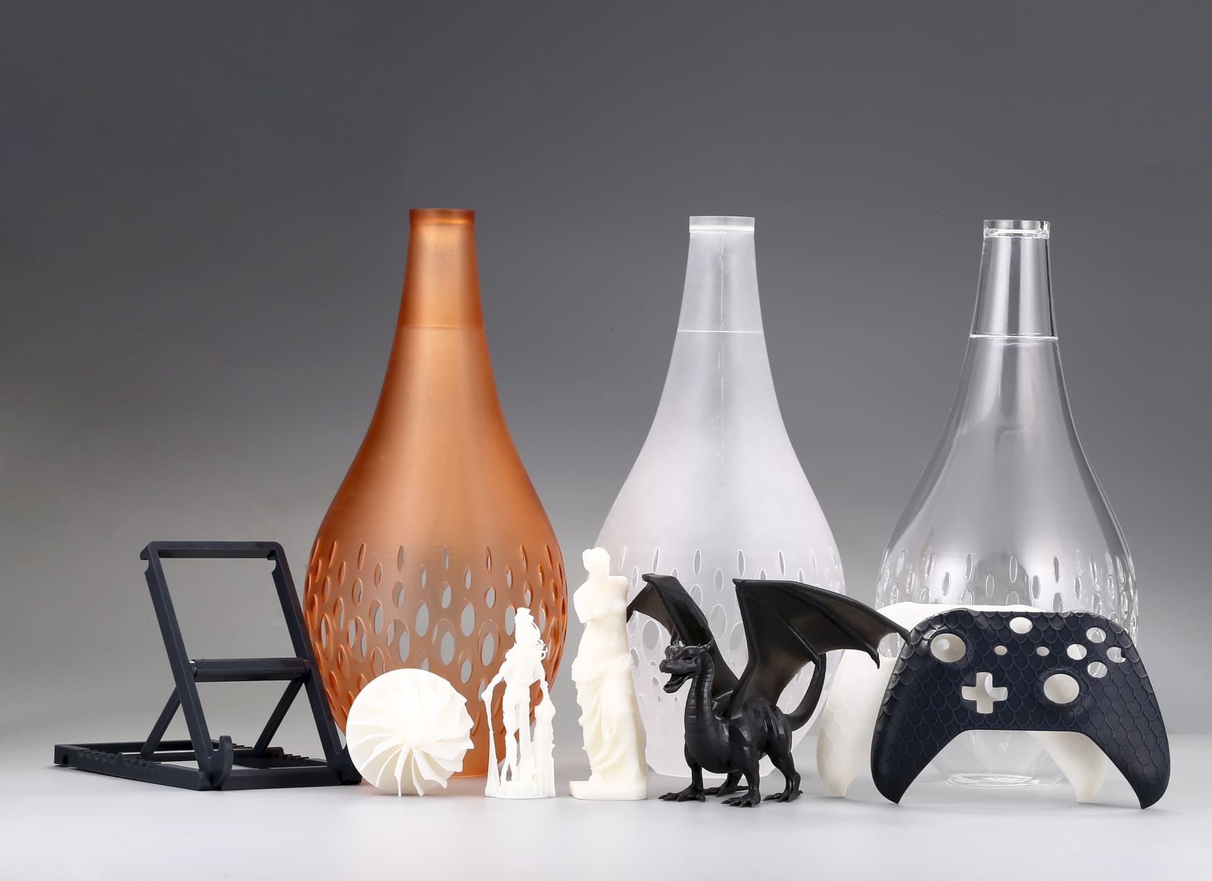
Top 8 Design Rules
1. Minimum Wall Thickness
Safe default: 0.8 mm. Thin walls down to 0.5–0.6 mm may print with some resins, but risk fragility and warping. For functional/stress-bearing walls, use ≥1.0 mm.
2. Minimum Feature Size
Fine features (thin fins, tiny bosses) should be ≥0.5–0.7 mm. Anything smaller may not cure reliably or will be brittle after post-cure.
3. Minimum Hole Diameter & Slots
Printed holes: 0.8–1.2 mm minimum. Plan to drill/ream holes smaller than ~1.5 mm for best accuracy. Slots should be designed ≥0.5 mm wider than the intended final fit (to allow for resin and support contact).
4. Unsupported Overhangs & Angles
Keep free-hanging surfaces above 45° from horizontal where possible. Shallow angles require supports; very small cantilevers often fail.
5. Bosses, Ribs and Webs
Boss diameters should be at least 2.5× the nominal screw size root. Ribs add stiffness — keep rib thickness ≤50% of the adjoining wall thickness and add fillets to avoid stress concentrators.
6. Internal Cavities & Drainage
Add drain/vent holes for trapped resin in closed cavities. Typical drain hole sizes: 2–3 mm for manual draining; multiple 1–2 mm vents can work if space is tight.
7. Threads and Inserts
Avoid printing fine machine threads directly. For metal-thread performance, print oversized sacrificial threads and tap afterwards, or design for heat-set/press-fit inserts.
8. File Export & Mesh Quality
Export binary STL, keep chordal tolerance ≤0.05 mm and check for non-manifold edges. Clean meshes prevent slicer surprises and small facets on curved surfaces.
(The exact minima vary by resin, printer resolution, layer thickness and slicer: always confirm with the material datasheet and a printed test sample.)
Image Copyright © 3DSPRO. All rights reserved.
Best Orientations for Surface Quality
Surface Quality First
Orient the most visible/critical surface away from supports and minimize layer stair-stepping by angling flat surfaces slightly (10°–30°). Avoid horizontal flat faces that face the build platform directly; a slight tilt reduces visible layer bands.
Dimensional Accuracy First
Orient features that require tight tolerances parallel to the build platform (X–Y plane), where voxel resolution is highest. For pin holes and shafts, print them vertical if you need roundness; print them horizontal if you need length accuracy.
Support Removal and Aesthetics Balance
Orient so supports attach to non-critical or easily hidden faces. Long, thin features are usually best tilted slightly to reduce leverage during peeling.
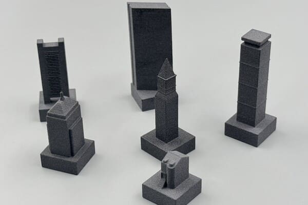
Packing/Throughput Considerations
When printing many small parts, orient to maximize packing density while keeping critical faces accessible for support removal.
Image Copyright © 3DSPRO. All rights reserved.
Supports Placement
Support Types & Contact Geometry
Use small point contacts where possible for minimal post-processing. For delicate areas, use wider “raft” or “tub” contacts. Specialty slicer settings (adaptive contact size, block supports) can reduce scarring.
Where to Attach Supports
Attach to flat, non-critical, easy-to-sand areas. Avoid placing supports inside mating surfaces, inside holes, or on thin ribs. If an internal surface must have supports, design sacrificial tabs that can be removed.
Density & Spacing
Higher density supports reduce print failure on steep faces but increase post-processing. Use more dense supports for large overhangs and fewer for small features.
Support Removal Strategy
Orient supports so they shear off cleanly. For fragile parts, consider using breakaway supports or printing a thin support “bridge” to protect delicate features.
Support Scars and Cosmetic Work
After removal, moderate sanding and a light fill (putty or resin) plus post-cure can hide marks. For jewelry or display parts, design small fillets or recesses where supports will attach to hide scars.
Image Copyright © 3DSPRO. All rights reserved.
Post-processing
Cleaning
Rinse parts in isopropyl alcohol (70–99% commonly used) or approved solvents to remove uncured resin. Use multiple baths or agitation for complex geometries.
Drying
Allow parts to air-dry or use gentle compressed air. Ensure cavities and holes are free of solvent before curing.
Post-Cure (UV)
UV post-curing hardens polymer chains and stabilizes mechanical properties. Times and intensities vary — common practice: 2–20 minutes in a dedicated box, depending on lamp power and resin. Follow the resin datasheet for recommended cure cycles.
Sanding, filing, or micro-milling removes support scars. For smooth surfaces, progressively sand with finer grits and consider a light resin brush coat and re-cure to fill fine scratches.
Thermal and Chemical Considerations
Some engineering resins require thermal post-cure or annealing. Avoid aggressive solvents for long periods — they can swell or soften prints.
Coatings and Plating
For improved surface finish or functional needs, apply primers, paints, or conductive coatings. For casting patterns, use appropriate coating steps to enable burnout.
Image Copyright © 3DSPRO. All rights reserved.
Tolerances
Typical achievable tolerances
• General features: ±0.1–0.3 mm.
• Small features (<5 mm): expect larger relative variation; plan for ±0.1–0.2 mm.
• Holes and shafts: expect +/–0.1–0.2 mm; small holes may print undersized and need reaming.
How to Specify Tolerances
Call out critical dimensions on drawings and specify how they’ll be achieved (e.g., “hole to be drilled to Ø3.0 ±0.05 mm after print”). If post-processing (drilling, tapping, inserts) is used, indicate that in the BOM.
Compensating for Shrinkage
Post-cure shrink or thermal effects are typically 0.1–0.5% of dimension depending on the resin. For critical fits, print test coupons and measure after full post-processing to derive correction factors.
Fit Recommendations
Press fits: design for 0.1–0.2 mm interference, depending on material stiffness and insert type. Clearance fits: allow 0.15–0.3 mm clearance for moving parts, more for small parts.
Image Copyright © 3DSPRO. All rights reserved.
 4
4


COMMENTS
- Be the first to share your thoughts!