Core Advantages of SLS for Design
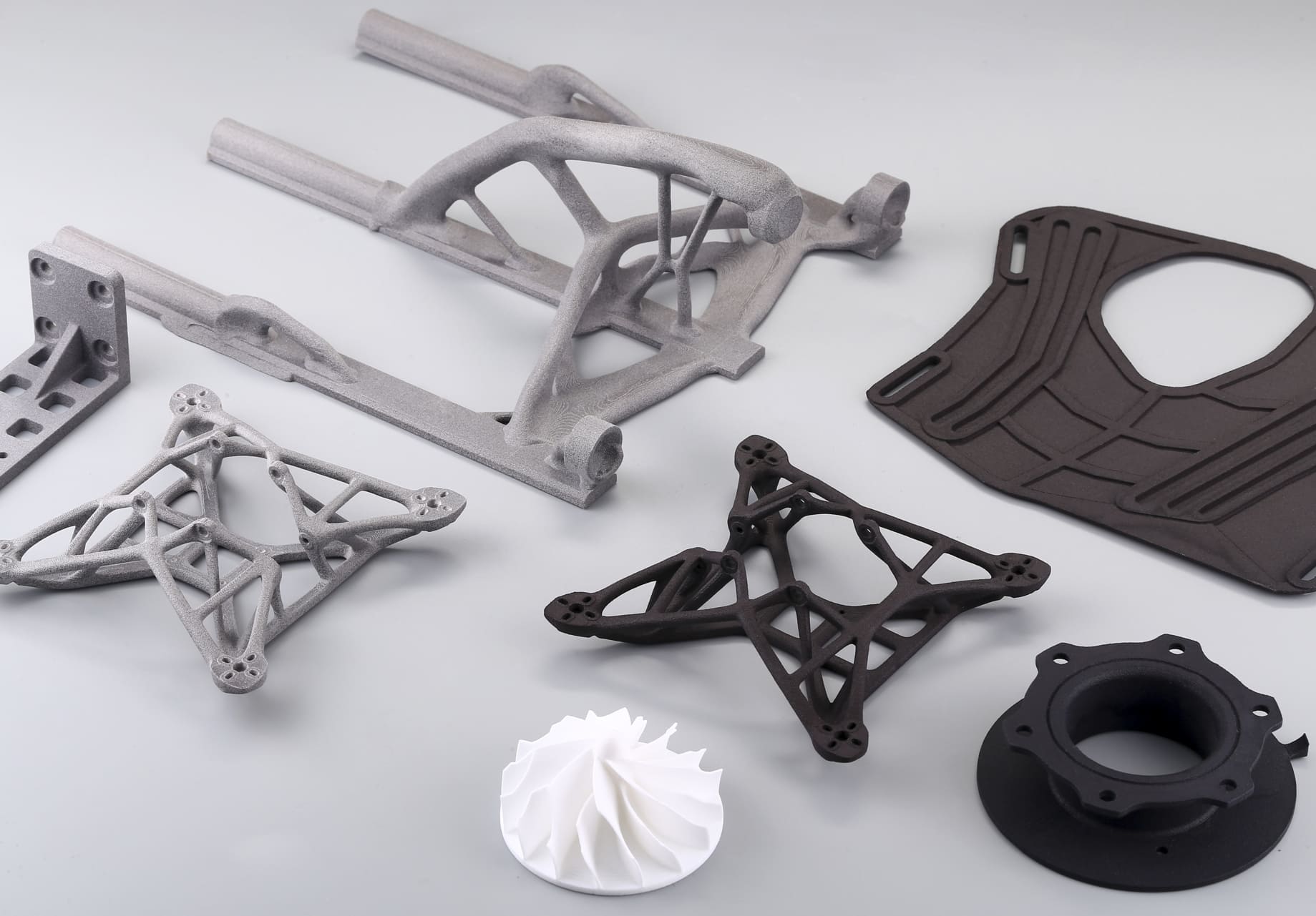
Selective Laser Sintering (SLS) is a powder‑bed fusion technology that uses a high‑powered laser to fuse polymer particles layer by layer. Unlike FDM or SLA, SLS builds parts without the need for dedicated support structures, as the surrounding unsintered powder acts as a natural support medium.
Key advantages include:
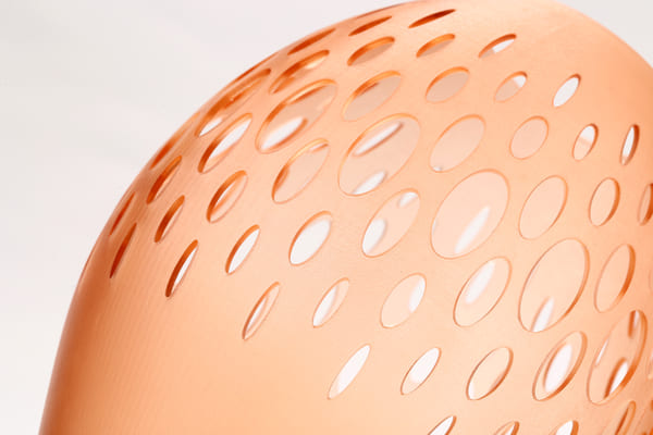
Exceptional Geometric Freedom
Designers can create complex assemblies, interlocking parts, internal channels, and organic shapes that would be impossible or prohibitively expensive with subtractive methods.
Material Variety & Performance
SLS supports a range of engineering‑grade thermoplastics like PA12, PA11, glass‑filled nylon, and TPU. Each material offers unique mechanical properties, enabling applications from rigid housings to flexible gaskets.
Strength & Durability
With near‑isotropic mechanical properties, SLS parts perform well under load and exhibit high impact resistance, making them suitable for functional prototypes and end‑use products.
Scalability for Production
Multiple parts can be nested and printed together in a single build, improving throughput and enabling low‑to‑mid‑volume manufacturing.
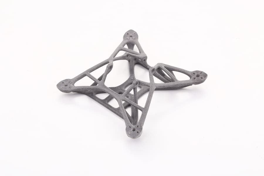
Image Copyright © 3DSPRO. All rights reserved.
Design Considerations for SLS
1. Minimum Wall Thickness
• PA12: ~1.0 mm for self‑supporting walls; 1.5–2.0 mm for large flat spans to prevent warping.
• Flexible Materials: 1.2–1.5 mm minimum to maintain structural stability.
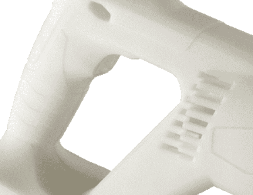
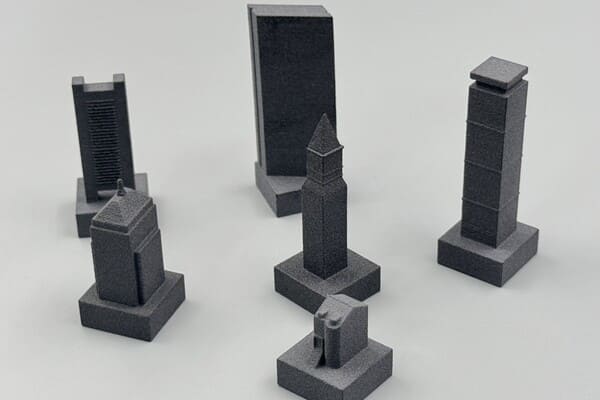
2. Feature Size & Resolution
• Embossed Details: ≥0.5 mm depth and width.
• Engraved Details: ≥0.5 mm depth for legibility post‑processing.
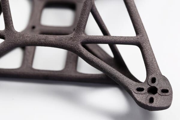
3. Internal Channels & Cavities
• Include Powder Escape Holes: at least 2 × 5 mm diameter or larger for efficient depowdering.
• Avoid blind internal voids where powder cannot be removed.
4. Overhangs & Complex Geometry
• No dedicated supports are required, but sharp overhang edges <1 mm can fuse poorly and you'll need to add chamfers or fillets.
5. Warping & Shrinkage Compensation
• Nylon materials shrink ~0.3% during cooling; apply CAD scaling or tolerance allowances accordingly.
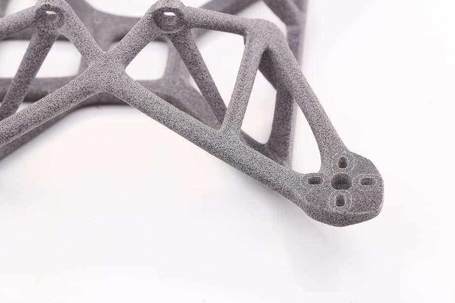
Image Copyright © 3DSPRO. All rights reserved.
Tolerances & Accuracy
SLS produces parts with high dimensional fidelity, but factors like laser spot size and thermal contraction impact precision.
Typical Tolerance Ranges
• ±0.3 mm for features <100 mm
• ±0.3% for dimensions >100 mm
Accuracy is Influenced by:
• Layer Thickness: Commonly 0.1 mm, balancing resolution and build time.
• Thermal Management: Uneven heat distribution can cause slight warping.
• Material Choice: Filled nylons typically offer better stiffness and less warping than unfilled PA12.
Post‑Processing for Precision:
For critical mating parts, apply secondary machining (CNC or reaming) to achieve tight fits.
Image Copyright © 3DSPRO. All rights reserved.
Optimizing for Mechanical Performance
SLS allows for orientation control and internal structuring to maximize strength and usability.
1. Part Orientation
• Align load‑bearing features with the XY plane for better tensile strength.
• Vertical (Z‑axis) orientation may have slightly reduced strength but offers better flatness for certain surfaces.
2. Functional Reinforcements
• Add ribs to thin panels for stiffness without drastically increasing mass.
• Use gussets at joint intersections for better load distribution.
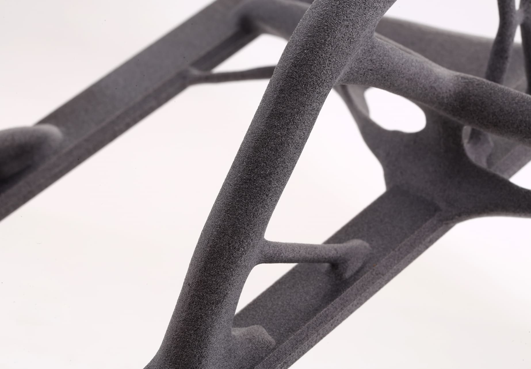
3. Lattice Structures
• Incorporate lightweight lattices to reduce material usage while maintaining rigidity.
• Ideal for applications where the weight‑to‑strength ratio is critical (e.g., aerospace brackets).
4. Wear & Fatigue Resistance
• Select PA11 or composite‑filled materials for repetitive stress applications.
Common Design Mistakes to Avoid
Skipping Powder Escape Planning
Hollow parts without escape holes trap unsintered powder, adding unnecessary weight and cost.
Underestimating Clearance Needs
For assemblies, allow at least 0.5 mm clearance between moving parts to ensure post‑print mobility.
Flat, Unsupported Surfaces
Large, thin planes may warp. Introduce slight curves or structural reinforcements.
Overtight Fits Without Post‑Machining
SLS tolerances are good, but not injection‑mold precision — design for fit adjustment post‑printing if needed.
Neglecting Post‑Processing Impact
Dyeing, vapor smoothing, or bead blasting can subtly alter dimensions; factor these into designs.
Cost Optimization Strategies
1. Efficient Nesting & Orientation
• Position parts tightly without risking heat buildup between components.
• Stagger orientations to optimize laser pathing and reduce warp risk.
2. Hollowing & Weight Reduction
• Create shell structures with adequate wall thickness.
• Use honeycomb or lattice infills to cut down on powder consumption.
3. Powder Reuse Rates
• Design with material refresh rates in mind; high‑reusability materials reduce waste and per‑part costs.
4. Batch vs. Single Runs
• Group similar parts in one build to maximize machine utilization.
5. Post‑Processing Efficiency
• Choose finishing methods strategically — avoid over‑specifying surface treatments that add cost without functional benefit.
 0
0


COMMENTS
- Be the first to share your thoughts!