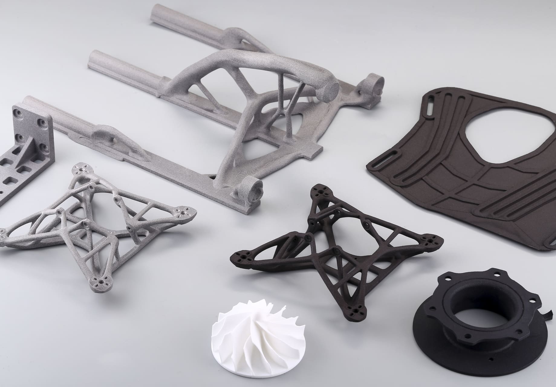
Core Advantages of MJF for Design
1. No Support Structures Required
The surrounding powder fully supports overhangs and complex geometries, eliminating support scars, reducing post-processing, and unlocking enclosed channels, internal lattices, and nested assemblies. Plan powder escape paths for closed volumes to keep parts lightweight and clean.
2. High Dimensional Accuracy
• Typical tolerances: ±0.3% (minimum ±0.3 mm)
• Consistent accuracy across the build volume, making it suitable for functional prototypes and end-use parts.
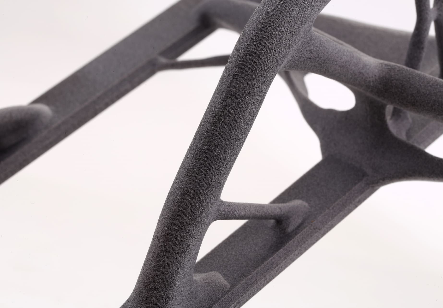
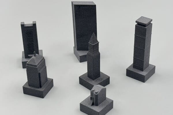
3. Fine Feature Resolution
• Layer thickness of 80 μm allows for crisp details, small text, and intricate geometries.
• Excellent for parts with small holes, embossed/engraved features, and complex surface textures.
4. Isotropic Mechanical Properties
• Uniform strength in all directions due to the powder bed fusion process.
• Ideal for load-bearing applications and mechanical assemblies.
5. Fast Production Speeds
• Entire layers are fused simultaneously, enabling faster turnaround than point-by-point laser systems.
• Well-suited for low-to-mid volume production.
6. Material Versatility
• Common options: PA12, PA11, PA12 Glass Bead (GB), TPU.
• Each material offers distinct mechanical and thermal properties, enabling a wide range of applications.
Copyright © 3DSPRO. All rights reserved.
General Design Considerations for MJF
1. Wall Thickness
• Supported walls: ≥ 0.5 mm
• Unsupported walls: ≥ 1.0 mm
• Thicker walls improve strength but increase weight and cost.
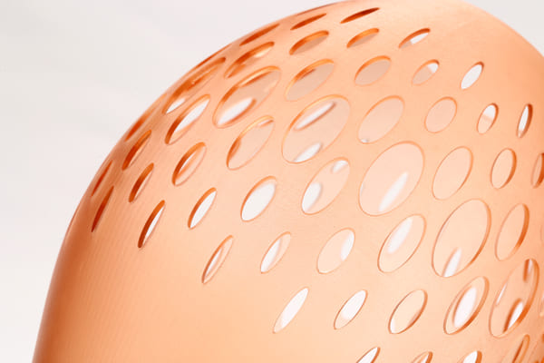
2. Holes & Channels
• Minimum hole diameter: 1.0 mm for through-holes.
• For enclosed channels, add escape holes (≥ 2 mm) for powder removal.
3. Text & Details
• Embossed/engraved text: ≥ 0.5 mm depth/height for legibility.
• Use sans-serif fonts for better readability.
4. Part Orientation
• Orient parts to minimize visible layer lines on critical surfaces.
• Consider load direction for mechanical performance.
5. Shrinkage & Warping
• MJF parts typically shrink ~0.4% during cooling.
• Avoid large flat surfaces without reinforcement to reduce warping.
Copyright © 3DSPRO. All rights reserved.
Assembly & Multi-Part Printing
1. Printing Assemblies in One Build
• Possible to print moving parts fully assembled.
• Maintain 0.5 mm clearance between moving surfaces to prevent fusion.
2. Tolerances for Fits
• Press-fit: 0.1–0.2 mm interference.
• Slip-fit: 0.2–0.5 mm clearance.
• Test with prototypes before committing to production.
3. Modular Design
• Split large parts into smaller modules for easier printing and post-processing.
• Use interlocking features or mechanical fasteners for assembly.
4. Powder Removal in Assemblies
• Ensure adequate escape holes for enclosed spaces.
• Design internal channels with smooth curves to aid powder flow.
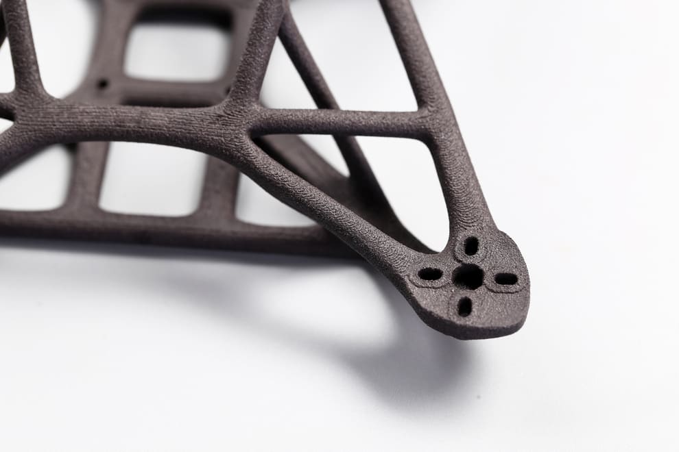
Lightweighting & Internal Structures
1. Hollowing Strategies
• Hollow thick sections to save material and reduce cost.
• Maintain ≥ 2 mm wall thickness for structural integrity.
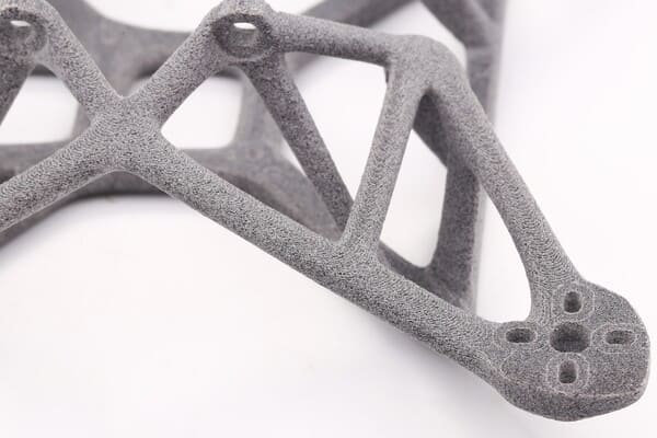
2. Lattice Structures
• Use lattice infills to maintain stiffness while reducing mass.
• Consider gyroid or diamond lattices for balanced strength and powder removal.
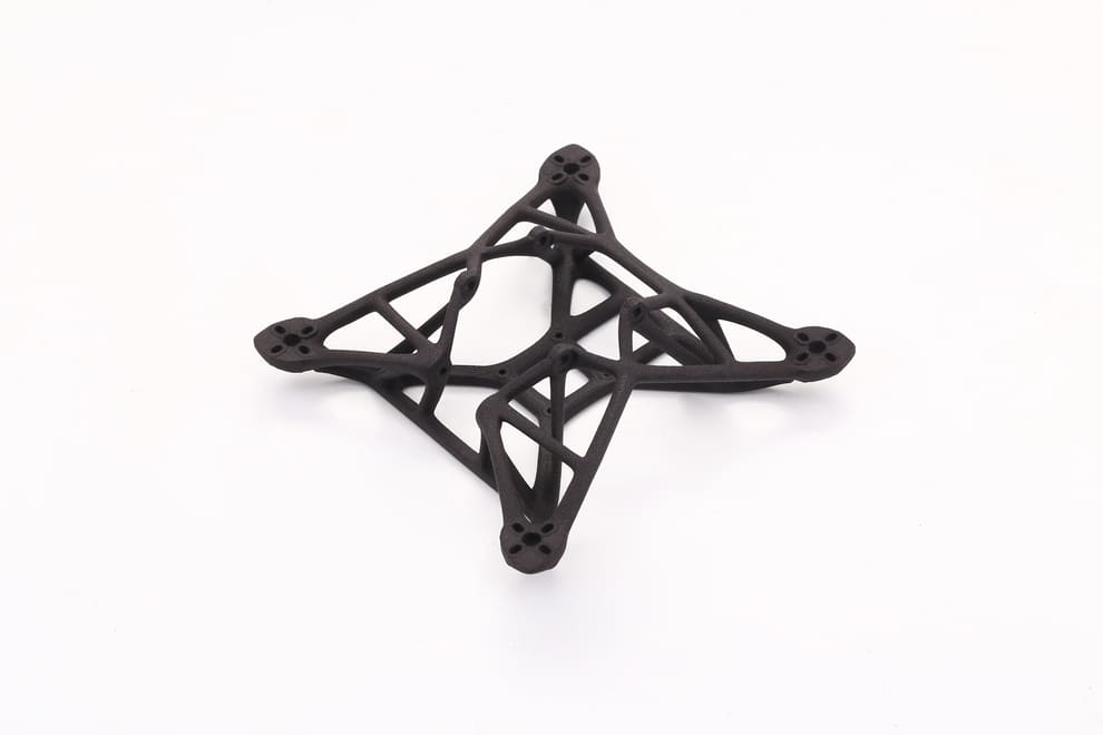
3. Topology Optimization
• Use simulation tools to remove non-critical material.
• Combine with MJF’s ability to print complex geometries for maximum efficiency.
4. Powder Removal Considerations
• For hollow or lattice-filled parts, include multiple escape holes (≥ 2 mm).
• Position holes in non-critical areas for aesthetics.
Common Design Mistakes to Avoid
1. Ignoring Minimum Feature Sizes
• Features below the recommended limits may fuse, break, or fail to print.
2. Overlooking Powder Escape
• Enclosed powder can add weight, affect balance, and trap heat during post-processing.
3. Unsupported Thin Walls
• Thin, tall walls without bracing can warp or break during depowdering.
4. Overly Tight Tolerances
• Designing with injection molding tolerances can lead to assembly issues.
• Always account for MJF’s ±0.3% dimensional variation.
5. Neglecting Post-Processing Allowances
• Dyeing, vapor smoothing, or coating can add thickness; plan for it in CAD.
Cost Optimization Strategies
1. Nesting & Build Volume Utilization
• Arrange parts efficiently in the build chamber to maximize throughput.
• Stack parts vertically when possible, leaving enough clearance for powder removal.
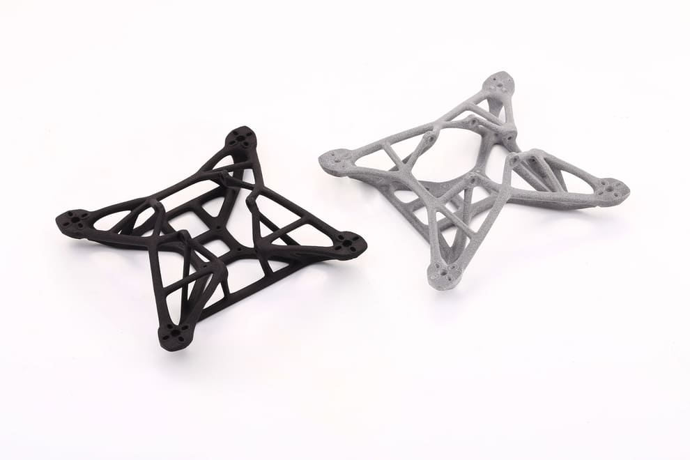
2. Material Selection
• Choose the right material for the application: PA12 for general use, PA12 GB for stiffness, PA11 for impact resistance, and TPU for flexibility.
• Avoid over-specifying materials that increase cost unnecessarily.
3. Reduce Part Volume
• Hollowing and lattice structures not only reduce weight but also lower material usage.
• Minimize solid mass in non-critical areas.
4. Combine Parts
• Consolidate multiple components into a single printed part to reduce assembly labor and fasteners.
5. Optimize Wall Thickness
• Thicker walls increase cost; use the minimum thickness that meets performance requirements.
6. Batch Production
• Printing multiple parts in one build reduces per-part cost.
• Group similar parts to streamline post-processing.
Copyright © 3DSPRO. All rights reserved.
 0
0


COMMENTS
- Be the first to share your thoughts!