Treating post-processing as part of your CAD workflow reduces rework, shortens lead time, and produces parts that meet both functional and cosmetic targets.
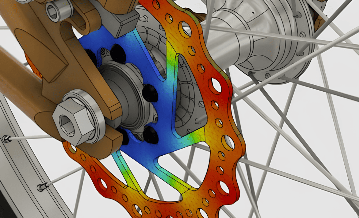
Image Source: Autodesk
How Common Post-Processing Change CAD Decisions
Support Removal
Supports create localized stresses during removal. CAD should give technicians room to access and pry supports without damaging thin walls or adjacent features. Consider sacrificial tabs or scalloped support transition zones in your model.
Sanding and Filing
Manual abrasion removes material unevenly. Designers must provide an allowance where material will be taken off, avoid fragile thin ribs in sanding zones, and prefer larger fillets and radii that are easier to sand smoothly.
Processes like acetone smoothing for ABS require access for solvent and avoiding enclosed cavities that trap liquids; surfaces must be continuous and free of tiny crevices where solvents pool.
Paint adds thickness and may obscure tight fits. Add allowances for coating build-up and design masking grooves or seams to hide transitions.
Machining and Tapping
If post-print machining is planned, CAD must include machining allowances, clear datum faces for fixturing, and oversized bosses/holes that get finished to the final size.
Inserts and Heat-Staking
Boss geometry and wall thickness must support insert installation and thermal loads.
CAD Rules and Strategies
Model Two Bodies: As-Printed and Finished
Maintain an as-printed body (exported to STL) and a finished body that reflects material removed or added (machined faces, paint thickness), which makes outputs explicit for fabricators and inspectors.
Use Parameterized Finishing Allowances
Create parameters for sanding allowance, machining allowance, and coating thickness. Drive local offsets with those parameters so you can update globally if the finishing plan changes.
Tag Functional vs Cosmetic Surfaces
Add attributes/metadata to surfaces in your CAD (or on drawings) that mark them as “functional — tight tolerance” or “cosmetic — visual only,” which tells the post-processing team where to concentrate effort.
Design Access Ports and Escape Paths
For enclosed cavities or long channels that need support removal or solvent flow, add holes or sacrificial plugs positioned for easy access.
Include Sacrificial Features Intentionally
Sacrificial tabs, ribs, or breakaway sections protect critical geometry during support removal or fixturing. Make them obvious in the CAD and removable without altering adjacent surfaces.
Favor Robust Fixturing Faces
Add broad, flat reference faces for clamping and measurement. If machining will follow, include datums sized and shaped to match fixture plates.
Model Inserts and Fastener Features from Standard Templates
Use library geometry for heat-set inserts, threaded inserts, and snap fits to ensure reliable post-processing and assembly.
Tolerance and Dimensioning Guidance
Separate cosmetic and functional tolerances. Don’t waste tight tolerances on visible surfaces that only need to look good; reserve precision for mounting faces, sealed interfaces, and mechanical interfaces.
Use realistic finishing allowances. Typical paint/primer build-up varies widely, but a useful starting note is 0.05–0.3 mm per coat, depending on method. For machining allowances, start with 0.5–1.5 mm of surplus for material removal, reduced for thin features or high-precision processes.
Specify GD&T for critical fits. When fit matters, use GD&T datums defined on the finished geometry. Call out runout, perpendicularity, and position relative to the finished faces, not the raw printed surfaces.
Dimension for post-process variability. Where possible, specify functional clearances instead of exact hole sizes when the hole will be tapped later. For threads formed into printed plastic, include thread engagement and wall thickness requirements.
Document the inspection method. Indicate whether dimensions are measured before or after finishing, and the acceptable measurement technique.
Process-Specific CAD Recommendations
Sanding
• Add a local sanding allowance as an offset and avoid thin flanges in sanding zones.
• Use larger fillets (≥0.5 mm where practical) and remove tiny radii that trap grit.
• Provide clamping flats adjacent to sanding areas.
Painting and Coating
• Design masking grooves and consistent seams to conceal paint edges.
• Avoid deep, narrow cavities where paint pools, add gentle tapers (1–3°) and drains if necessary.
• Specify coating thickness notes in the CAD metadata.
Chemical Smoothing
• Don’t enclose dead-end cavities without vents. Add smooth radii and avoid abrupt changes that trap solvent.
• Make accessible test coupons to validate aesthetics first.
Plating
• Include vent/escape holes sized to the part geometry and plating chemistry.
• Model any sacrificial attachment points for racks or fixtures used during plating.
Machining
• Model bosses and pads oversized by your machining allowance and include clamping datums.
• For tapped holes, model pilot holes or clearances so the machinist can locate and produce the final thread.
Inserts
• Use standard insert pocket geometry with chamfers and lead-ins.
• Confirm wall thickness around inserts meets vendor specs to avoid cracking during installation.
Exporting, Mesh Settings and Hand-Off Notes
Export both CAD and printable mesh. Provide a STEP/IGES for engineering and an STL/AMF for the print team. Label files clearly.
Mesh resolution matters. Choose a tessellation that preserves the intended radii without creating huge files. Small fillets need tighter STL settings; functional faces can tolerate coarser meshes.
Attach manufacturing notes. Embed or accompany files with a short finish sheet, such as finishing processes, expected coating thicknesses, sanding allowance, machining allowance, and critical datums.
Provide sample coupons. Supply a small printed coupon showing layer orientation, support interface, and a representative finish sample so the finishing team knows the target.
Use version control. Track which model corresponds to which finishing plan so changes are traceable and reproducible.
 0
0


COMMENTS
- Be the first to share your thoughts!