General Design Considerations for SLM
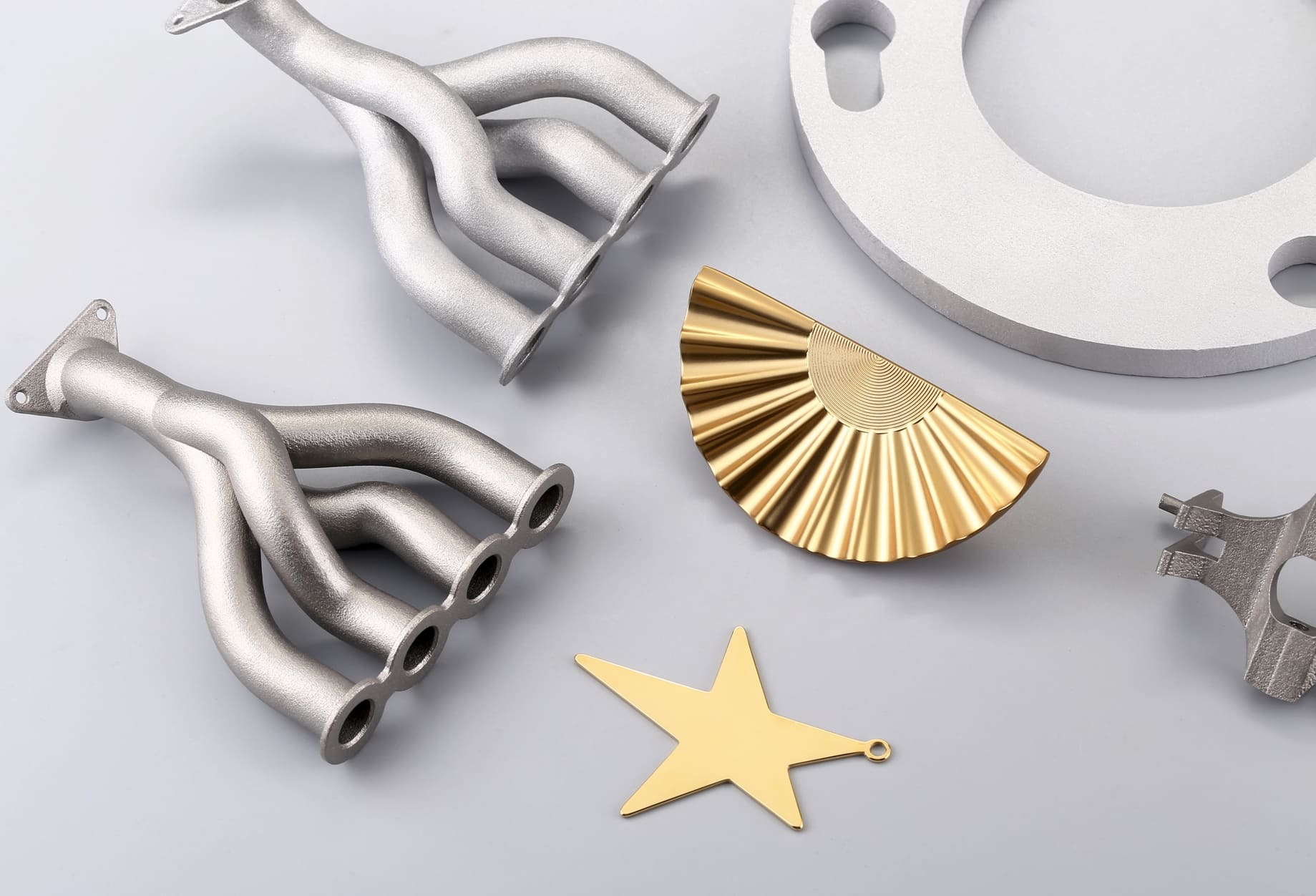
SLM uses a high-powered laser to selectively melt fine metal powder layer by layer. While this allows for exceptional precision and complexity, the process has unique constraints that influence design.
Material Selection
1. Common SLM materials: Stainless steel, titanium alloys, aluminum alloys, cobalt-chrome, Inconel.
2. Choose materials based on mechanical requirements, corrosion resistance, and thermal properties.
3. Consider post-processing needs (e.g., titanium may require stress relief heat treatment).
Wall Thickness
1. Minimum wall thickness: Typically 0.5–1.0 mm for structural integrity.
2. Thin walls risk warping or incomplete fusion; thicker walls increase build time and cost.
3. For load-bearing parts, aim for ≥2 mm thickness.
Overhangs & Support Structures
1. Overhangs greater than 45° from vertical generally require supports.
2. Minimize supports to reduce post-processing time and surface blemishes.
3. Design self-supporting angles where possible.
Tolerances & Accuracy
1. Typical dimensional accuracy: ±0.1–0.2 mm.
2. Account for shrinkage and thermal distortion in CAD models.
3. Critical surfaces may require CNC machining after printing.
Orientation
1. Part orientation affects surface finish, strength, and support requirements.
2. Vertical orientation reduces footprint but may increase build height and time.
3. Horizontal orientation can improve accuracy for certain features.
Copyright © 3DSPRO. All rights reserved.
Assembly & Multi-Part Printing
Modular Design
1. Break large parts into smaller modules to fit within the build chamber.
2. Allows for easier handling, reduced risk of build failure, and faster iteration.
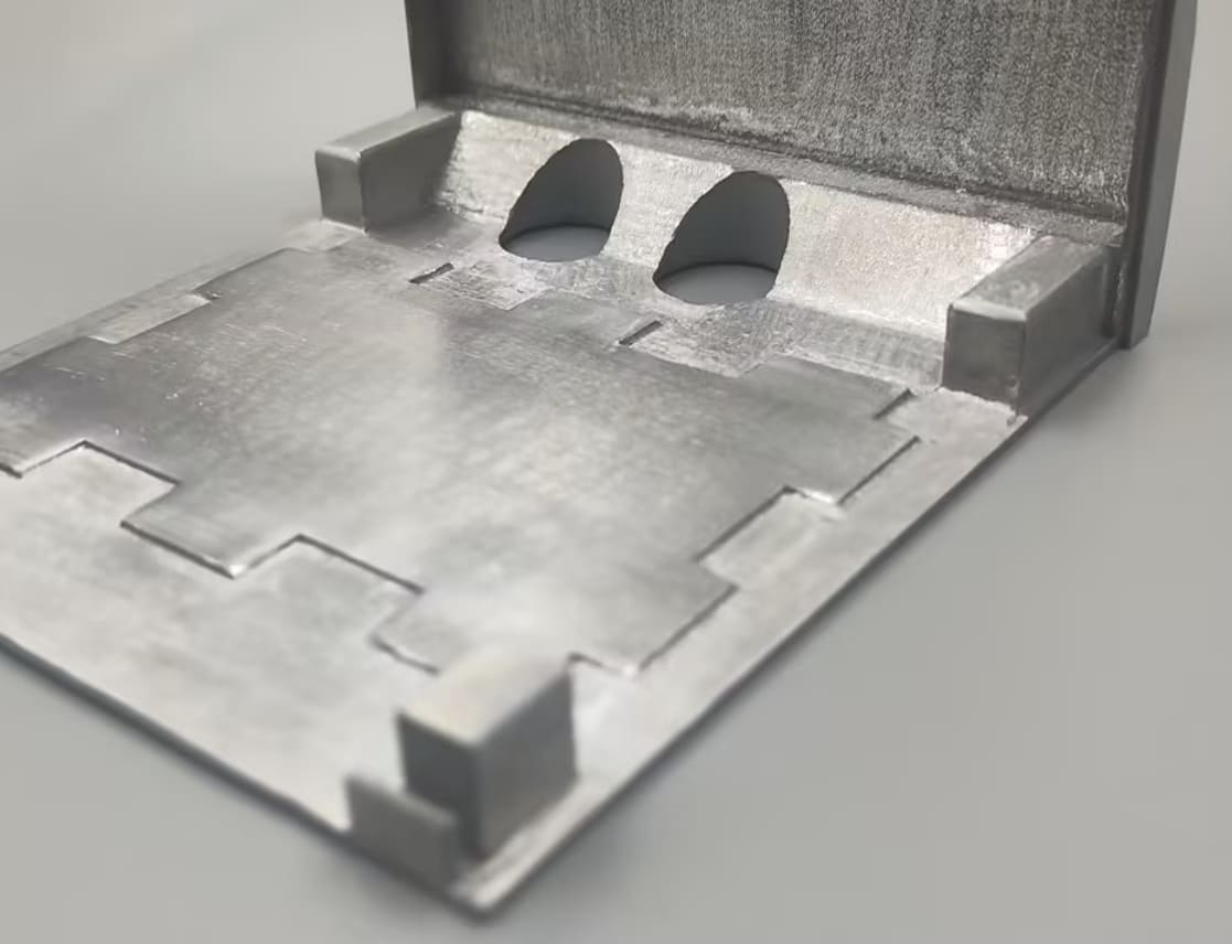
Integrated Fastening Features
1. Design built-in threads, slots, or dovetails for mechanical assembly.
2. Avoid overly fine threads — post-process tapping may be required.
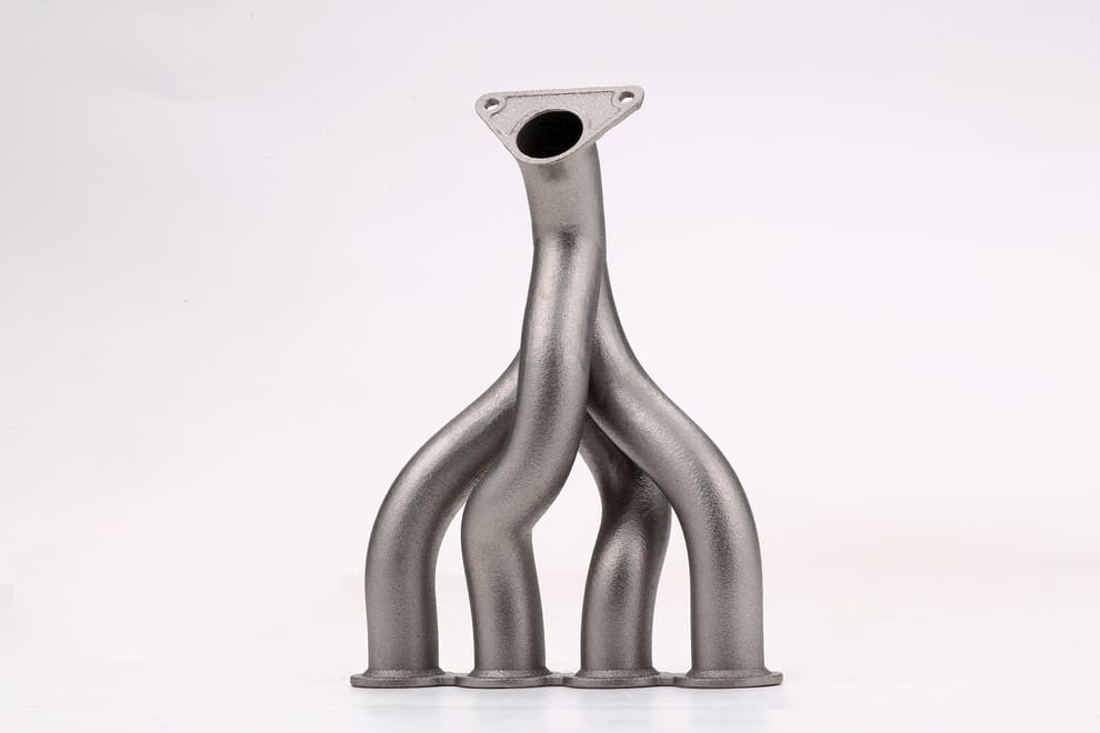
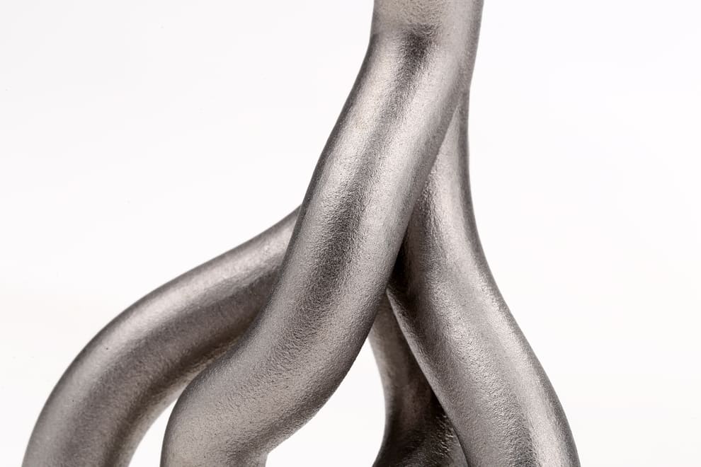
Hybrid Manufacturing
1. Combine SLM components with conventionally manufactured parts.
2. Example: Print complex internal manifolds, then attach to machined flanges.
Alignment & Fit
1. Include locating pins, keyways, or alignment tabs for precise assembly.
2. Allow for tolerance stack-up in multi-part designs.
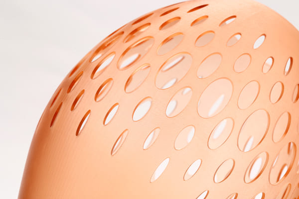
Complex & Internal Structures
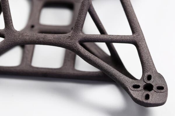
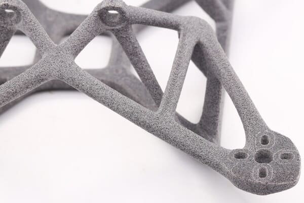
Lattice Structures
1. Reduce weight while maintaining strength.
2. Common lattice types: Gyroid, Octet, Diamond.
3. Use simulation tools to optimize lattice density for load paths.
Internal Channels
1. Ideal for cooling systems, fluid flow, or weight reduction.
2. Maintain a minimum channel diameter of 2–3 mm to ensure powder removal.
3. Avoid sharp internal corners — use fillets to improve flow and reduce stress.
Conformal Cooling
1. Channels follow the contour of the part for uniform temperature control.
2. Widely used in injection mold tooling to reduce cycle times.
Powder Removal Considerations
1. Design escape holes for trapped powder.
2. Position holes in accessible areas for cleaning tools or compressed air.
Common Design Mistakes to Avoid
|
Mistake |
Why It’s a Problem |
How to Avoid |
|
Ignoring Support Needs |
Leads to failed builds or poor surface finish |
Design self-supporting angles, minimize overhangs |
|
Too Thin Walls |
Warping, incomplete fusion |
Keep walls ≥0.5 mm, thicker for load-bearing |
|
No Powder Escape Routes |
Trapped powder affects performance |
Add cleaning holes ≥2 mm diameter |
|
Overly Tight Tolerances |
SLM has limits on accuracy |
Allow ±0.1–0.2 mm, machine critical surfaces |
|
Complexity Without Purpose |
Increases cost & build time |
Use complexity only where it adds value |
Cost Optimization Strategies
Reduce Material Volume
• Use hollow sections, lattices, and internal channels.
• Avoid solid blocks unless structurally necessary.
Minimize Supports
• Orient parts to reduce overhangs.
• Design self-supporting geometries.
Consolidate Parts
• Combine multiple components into a single print to reduce assembly time.
• Example: Integrate brackets, mounts, and housings into one part.
Batch Printing
• Print multiple parts in one build to maximize machine utilization.
• Use nesting strategies to fit more parts in the build chamber.
Post-Processing Efficiency
• Design for minimal machining and polishing.
• Avoid inaccessible internal surfaces that require manual finishing.
Copyright © 3DSPRO. All rights reserved.
FAQs
Q: What’s the difference between SLM and DMLS?
A: SLM fully melts the powder into a homogeneous solid, while Direct Metal Laser Sintering (DMLS) sinters powder particles together. SLM is generally used for single-alloy materials, DMLS for multi-alloy blends.
Q: How small can features be in SLM?
A: Minimum feature size is typically 0.3–0.5 mm, depending on material and machine settings.
Q: Do I always need support in SLM?
A: Not always. Self-supporting angles and certain lattice structures can eliminate the need for supports.
Q: Can SLM parts be used without post-processing?
A: Yes, for non-critical applications. However, most functional parts benefit from machining, heat treatment, or surface finishing.
Q: How do I choose the right orientation for my part?
A: Balance between minimizing supports, optimizing strength along load paths, and achieving the desired surface finish.
 1
1


COMMENTS
- Be the first to share your thoughts!