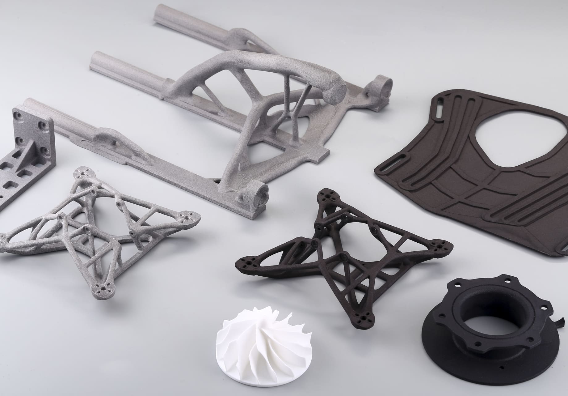
What is Anisotropy in 3D Printing Design?
In engineering, anisotropy refers to the directional dependence of a material’s mechanical properties. Unlike isotropic materials, which exhibit uniform strength and stiffness in all directions, anisotropic materials behave differently depending on the orientation of applied loads.
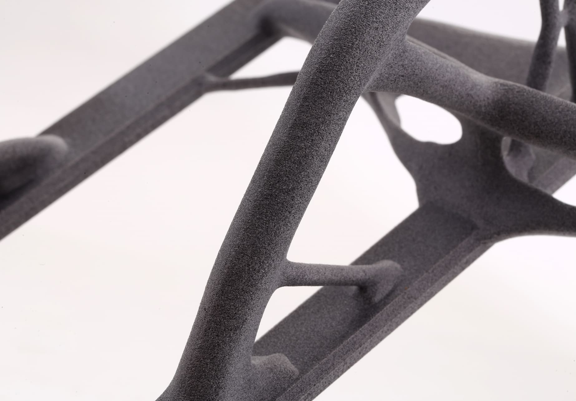
In the context of 3D printing (additive manufacturing), the layer-by-layer deposition process inherently introduces weak planes between layers, making the mechanical performance of printed parts highly dependent on build orientation, infill design, and bonding quality.
For engineers, this means that a part designed in CAD may not perform as expected if anisotropy is not accounted for. A bracket printed upright may fail under tensile load in the Z-direction, while the same bracket printed flat may withstand significantly higher stresses. Understanding anisotropy is therefore essential for functional prototyping, end-use parts, and safety-critical applications.
Image Source: Formlabs
Understanding Direction Dependent Mechanical Behavior
The anisotropic nature of 3D printed parts arises from three primary factors:
1. Layer Adhesion: Interlayer bonding is typically weaker than intralayer cohesion, creating planes of weakness.
2. Print Orientation: Mechanical loads aligned with the XY plane (parallel to layers) are generally better supported than loads applied along the Z-axis (perpendicular to layers).
3. Microstructural Variation: Cooling rates, crystallinity, and residual stresses vary across directions, further influencing performance.
Tensile and Flexural Properties
• In Fused Deposition Modeling (FDM), tensile strength in the XY plane can be up to 50% higher than in the Z direction.
• Flexural strength also varies, with bending resistance often reduced when the neutral axis crosses layer boundaries.
Fatigue and Impact Resistance
• Fatigue life is significantly shorter in the Z direction due to crack propagation along interlayer boundaries.
• Impact resistance is similarly reduced, as delamination occurs more readily under sudden loads.
For engineers, anisotropy is not a defect but a design parameter, one that must be quantified, predicted, and integrated into the design process.
Design Parameters Driving Anisotropy
Several design and process parameters directly influence anisotropy in 3D printed parts. Optimizing these parameters allows engineers to either mitigate anisotropy or strategically exploit it.
1. Build Orientation
• Flat Orientation (XY plane): Maximizes tensile and flexural strength but may increase print time and support requirements.
• Vertical Orientation (Z axis): Reduces footprint but introduces weak interlayer bonding.
• Angled Orientation: Balances strength distribution but complicates slicing and support strategies.
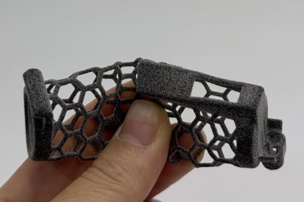
2. Infill Pattern and Density
• Rectilinear and Grid Infills: Provide predictable stiffness but limited energy absorption.
• Honeycomb and Gyroid Infills: Offer isotropic-like behavior in-plane and improved load distribution.
• High-Density Infill: Increases stiffness and strength but at the cost of weight and print time.
3. Layer Thickness and Extrusion Width
• Thinner Layers: Improve surface finish and interlayer adhesion but extend build time.
• Thicker Layers: Reduce print time but exacerbate anisotropy by creating larger interlayer gaps.
4. Support Structures and Overhangs
• Poorly designed supports can introduce stress concentrations and residual stresses, indirectly affecting anisotropy.
In practice, engineers must balance mechanical performance, print efficiency, and material usage when selecting these parameters.
Material Specific Anisotropy Considerations
Thermoplastics (PLA, ABS, Nylon, PETG)
• PLA: High stiffness but brittle; anisotropy manifests as sudden interlayer fracture.
• ABS: Better toughness but prone to warping; anisotropy influenced by cooling rates.
• Nylon: Excellent impact resistance; anisotropy is reduced when moisture absorption improves interlayer bonding.
Fiber-Reinforced Composites
• Short-Fiber Composites: Improve in-plane strength but may worsen Z-direction weakness.
• Continuous-Fiber Composites: Enable directional reinforcement, allowing engineers to “design” anisotropy for load paths.
Metals (SLM, EBM)
• Selective Laser Melting Printed Metal: Grain growth along the build direction creates anisotropy in yield strength and fatigue resistance.
• Electron Beam Melting Printed Metal: Elevated build temperatures reduce anisotropy but introduce residual stresses.
Ceramics and Advanced Polymers
• Ceramics exhibit extreme brittleness in the Z direction.
• High-performance polymers (PEEK, ULTEM) show reduced anisotropy due to higher processing temperatures and crystallinity control.
Engineering Strategies to Control Anisotropy
While anisotropy cannot be eliminated, it can be controlled, mitigated, or even leveraged through engineering strategies.
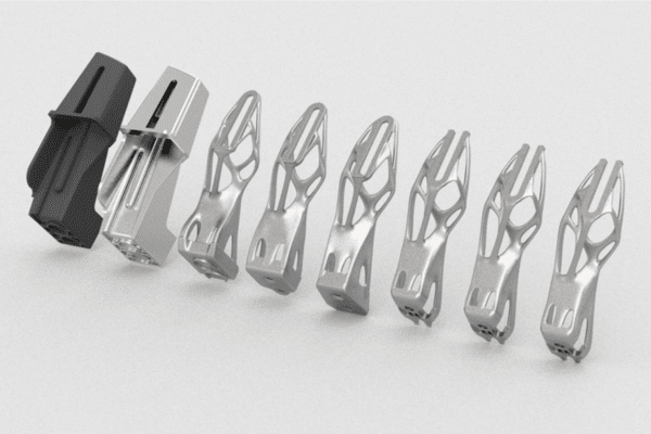
1. Design for Anisotropy
• Align critical load paths with the strongest print directions (XY plane).
• Use fillets and chamfers to reduce stress concentrations at interlayer boundaries.
• Incorporate redundant load paths to compensate for Z-direction weakness.
2. Process Optimization
• Increase extrusion temperature and reduce cooling rates to improve interlayer diffusion.
• Optimize raster angle to distribute stresses more evenly.
• Employ multi-axis 3D printing to reduce reliance on a single build direction.
3. Post-Processing Techniques
• Annealing: Relieves residual stresses and improves crystallinity.
• Infiltration: Resin or metal infiltration strengthens interlayer bonds.
• Hot Isostatic Pressing (HIP): For metals, it eliminates porosity and reduces anisotropy.
4. Simulation and Predictive Modeling
• Finite Element Analysis (FEA) tools now incorporate anisotropic material models.
• Predictive algorithms allow engineers to simulate failure modes before fabrication.
5. Standards and Testing Protocols
• ASTM D638 (tensile testing) and ISO 527 provide frameworks for anisotropy evaluation.
• Consistent testing across orientations ensures reliable data for design validation.
 28
28