English
 日本語
 Deutsch


Surface roughness affects the appearance, friction, wear, sealing, coating adhesion, and fit of CNC-milled parts. A smoother finish is not always necessary or economical; the right finish depends on the part’s function, material, and drawing requirements.
Cutting speed, feed per tooth, depth of cut, and stepover influence the surface left by a milling tool. Their effects also interact with tool geometry, machine rigidity, workholding, and tool wear. Understanding these relationships helps innovators meet finish requirements without unnecessary machining time or cost.
Surface Roughness in CNC Milling
Surface roughness describes the small peaks and valleys left on a machined surface. It differs from waviness, which refers to larger, more widely spaced variations, and from dimensional accuracy, which describes how closely a part matches its specified dimensions. A part can meet dimensional tolerances while still having an unsuitable surface finish.
Two common roughness parameters are Ra and Rz. Ra is the arithmetic average of the absolute deviations of a measured profile from its mean line. Rz describes peak-to-valley height over defined sampling lengths, according to the applicable measurement standard. Because the parameters describe different aspects of a profile, an Ra value alone may not reveal an isolated scratch or defect.
Surface roughness is commonly measured with a contact profilometer or suitable optical instruments. Results depend on measurement direction, evaluation settings, and location. For meaningful comparisons, use the same method and settings for each sample and measure across, rather than along, dominant tool marks where appropriate.
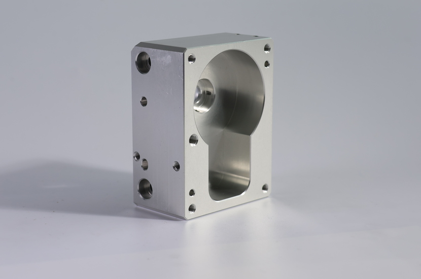
Image Copyright © 3DSPRO. All rights reserved.
How CNC Milling Parameters Affect Surface Roughness
Feed Rate and Feed per Tooth
Feed rate is how quickly the tool moves relative to the workpiece, commonly in millimeters per minute (mm/min). Feed per tooth (fz) is how far the workpiece advances between successive cutting edges, usually in millimeters per tooth. They are related by feed rate = spindle speed × number of teeth × feed per tooth.
Higher feed per tooth generally leaves more pronounced tool marks and can increase theoretical roughness. Reducing feed may improve the finish, but an excessively low feed can cause rubbing rather than effective cutting, contributing to heat and tool wear. Select a feed that suits the tool, material, and setup rigidity rather than simply using the lowest possible value.
Spindle Speed and Cutting Speed
Spindle speed is the cutter’s rotational speed in revolutions per minute (RPM). Cutting speed is the linear speed of the cutting edge relative to the workpiece, usually measured in meters per minute. It depends on spindle speed and tool diameter.
Increasing cutting speed can improve the finish in some materials by helping the tool shear material cleanly and reducing built-up edge. However, excessive speed can increase heat, accelerate wear, or trigger vibration. Too low a speed may encourage material adhesion or poor chip formation. Start with toolmaker recommendations for the specific material, then verify the result under actual machining conditions.
Axial Depth of Cut and Radial Width of Cut
Axial depth of cut is the distance the tool engages the workpiece along its axis; radial width of cut is the portion of cutter diameter engaged from the side. Both affect cutting forces, tool deflection, heat generation, and material removal rate.
Heavy cuts can increase deflection or vibration, leaving uneven marks or chatter. Depth of cut does not automatically determine roughness, however: a stable cut can produce a good surface while removing material efficiently. Roughing and finishing should have different objectives. Use roughing passes to remove material, then leave a consistent allowance for a lighter finishing pass.
Stepover and Finishing Toolpath
Stepover is the lateral distance between adjacent tool passes. It is particularly important when finishing curved surfaces with a ball-nose cutter. A large stepover leaves taller cusps between passes; reducing it generally creates a smoother surface but requires more passes and time. The relationship between stepover and cusp height depends on tool geometry and the surface.
For flat walls and floors, cutter geometry, runout, and toolpath strategy may matter as much as stepover. A finishing path should maintain consistent engagement and avoid abrupt changes that create marks at entry, exit, or direction changes. The smallest possible stepover is rarely the most economical choice; select one that meets the finish requirement.
Other Factors That Affect CNC Milling Surface Finish
✅ Tool geometry and condition: A sharp, suitable cutter helps form a clean surface. Tool material, coating, edge radius, flute count, corner radius, and runout influence cutting behavior. Worn or damaged edges may rub or leave irregular marks. A larger corner radius can improve theoretical finish in some operations, but may also increase cutting forces.
✅ Machine rigidity and workholding: Vibration and chatter are common causes of poor real-world finishes. Long tool overhang, flexible workpieces, weak clamping, spindle runout, or an unstable machine can produce marks that parameter changes alone will not fix. Secure the workpiece, minimize tool overhang, and check the tool holder and machine before repeatedly adjusting feeds and speeds.
✅ Material and chip evacuation: Different materials respond differently to identical settings. Soft, ductile materials may form a built-up edge, while harder materials can accelerate tool wear. Chips trapped in the cutting zone may be recut and scratch the surface. Appropriate coolant or lubrication, air blast, and chip evacuation help manage heat and remove chips, depending on the material and process.
How to Optimize CNC Milling Parameters for Better Surface Finish
Start with the drawing requirement. Identify the specified roughness, the surface that needs it, and whether the finish is functional or cosmetic. Avoid paying for a tighter finish than the part requires.
Choose a suitable cutter and begin with the tool manufacturer’s recommended cutting data. Keep tool stick-out as short as practical and support the workpiece firmly. Separate roughing from finishing so the finishing pass removes a consistent amount of material.
Change settings systematically. If the finish is poor, check tool wear, runout, chips, and vibration before changing multiple parameters. Then adjust one variable, such as feed per tooth, cutting speed, or stepover—while holding the others constant. A designed experiment can reveal interactions between parameters.
Measure results using the same profilometer settings and measurement direction, taking repeated readings at representative locations. Record the material, cutter, toolpath, settings, and measured Ra or Rz. This creates a basis for repeatable decisions instead of relying on visual judgment alone.
Finally, balance surface quality with productivity. A lower feed or smaller stepover may improve finish but increase cycle time; excessive speed can reduce tool life. The best setting reliably meets the drawing requirement while maintaining acceptable tool life, machining time, and cost.
CNC milling surface roughness depends on the combined effect of cutting parameters, tooling, material, and machine stability. Start with validated cutting data, make controlled adjustments, and verify the finish through consistent measurement. For custom CNC-machined parts, specifying the required surface finish helps align the process with the component’s function and budget.
 0