English
 日本語
 Deutsch


Bend radius is an important design parameter in sheet metal fabrication because it affects material deformation, springback, flat-pattern dimensions, and the geometry of the finished part. A radius that is too small can increase cracking risk, while a radius that is poorly matched to the material and tooling can make bend angles and flange dimensions harder to control.
Understanding these relationships helps engineers design manufacturable sheet metal parts, improve dimensional consistency, and reduce rework during production. However, bend radius must be considered alongside material properties, thickness, tooling, and the bending method.
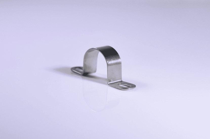
Image Copyright © 3DSPRO. All rights reserved
Understanding Bend Radius and Springback
What Is Sheet Metal Bend Radius?
The inside bend radius is the radius measured on the inner surface of a bent sheet metal part. It is typically specified alongside material thickness and bend angle on an engineering drawing. The actual radius produced depends on the material, punch and die geometry, and forming method.
During bending, material on the inside of the curve is compressed, while material on the outside is stretched. Between these regions lies the neutral axis, where longitudinal strain is approximately zero. Its position affects the length of material required to form the bend and therefore influences the flat pattern.
What Is Springback?
Springback is the elastic recovery that occurs after the bending force is removed. During forming, the sheet undergoes both elastic and plastic deformation. When the tooling releases the material, the elastic portion recovers, allowing the part to move partially toward its original shape. For a typical open bend, the included angle becomes larger after unloading.
Springback differs from errors caused by an incorrect blank size or inconsistent machine setup. It specifically describes the change in shape between the loaded and unloaded states, although that change ultimately affects finished-part dimensions.
Why Bend Radius Matters
Bend radius determines how deformation is distributed through the sheet thickness. A tight radius concentrates strain near the outer surface, increasing the risk of cracking, especially in less ductile materials or harder tempers. A larger radius generally reduces localized strain by spreading deformation over a wider region.
Radius also influences springback. Under otherwise comparable conditions, a higher ratio of inside bend radius to sheet thickness often produces greater springback. However, the relationship depends on material properties and forming conditions, so radius alone cannot predict the final bend angle.
How Bend Radius Affects Springback
The Relationship Between Radius and Elastic Recovery
Springback occurs because some of the material's strain remains elastic during bending and recovers after the punch releases the load. When the inside radius increases relative to sheet thickness, elastic recovery can have a greater influence on the final geometry. This may change both the bend angle and the radius after unloading.
A smaller radius may reduce springback in some forming conditions, but using the smallest possible radius is not a reliable strategy. Excessive strain can cause cracking, surface damage, or inconsistent results. The objective is to select a radius that provides the required geometry without exceeding the material's formability limits.
How Material Properties Influence Springback
Yield strength and elastic modulus play important roles in springback. Materials with higher yield strength generally require greater stress to produce permanent deformation and may exhibit more elastic recovery. A lower elastic modulus can also contribute to greater springback when other conditions are comparable.
Consequently, stainless steel, high-strength steel, and different aluminum alloys or tempers may behave differently under identical tooling conditions. Material thickness, work hardening, and bend angle also influence the outcome. For tight-tolerance parts, springback compensation should be based on the actual material specification and established forming data.
Tight vs. Large Bend Radii
A tight radius may suit a compact design, but it must meet material-specific minimum-radius requirements. An excessively small radius can cause cracking or thinning, particularly when the material has limited ductility.
A larger radius generally reduces strain concentration but may increase springback under otherwise comparable conditions. It also changes the geometry of the bend and can affect adjacent features. The best radius balances formability, springback, dimensional requirements, and available tooling rather than simply maximizing or minimizing the radius.
How Bend Radius Affects Dimensional Accuracy
Bend Angle and Springback Compensation
When springback opens a bend after unloading, manufacturers may need to form the sheet slightly beyond the target angle. This is known as overbending. The required compensation depends on the material, thickness, radius, bend angle, die opening, and forming method.
A fixed correction should not be applied to every part. Instead, manufacturers can use validated process data, press brake angle-control systems, or trial bends to establish the appropriate compensation. For parts with multiple bends, even small angle deviations can shift flange positions, misalign mounting holes, or affect assembly fit.
Bend Allowance and Flat-Pattern Accuracy
Bend radius also affects the developed length of the flat blank. Because the inside material compresses and the outside material stretches, the bend region cannot be calculated accurately by simply adding the finished flange dimensions.
CAD systems account for this using bend allowance or bend deduction, often with a K-factor. The K-factor represents the neutral-axis position as a fraction of material thickness. A common bend allowance formula is: BA = (π / 180) × A × (R + K × T)
Where:
• BA = bend allowance
• A = bend angle in degrees
• R = inside bend radius
• K = K-factor
• T = material thickness
As the radius changes, bend allowance changes as well. If the designed radius differs from the radius produced during fabrication, the flat-pattern calculation may be inaccurate, leading to incorrect flange dimensions. K-factor values depend on the material and forming process, so they should be validated for the production setup. SOLIDWORKS' K-factor guidance explains how the factor is used in bend allowance calculations.
Tooling and the Actual Bend Radius
The specified radius and the radius produced on a press brake may differ. In air bending, the V-die opening, material thickness, and material properties strongly influence the resulting radius; the punch nose radius alone does not always determine it. Bottoming and coining use different forming conditions and may produce different results.
For critical parts, coordinate the specified radius with the fabricator's tooling and verify the result on a first-off sample. This can prevent unnecessary special tooling and help ensure that the finished geometry matches the drawing.
Other Factors That Influence Bend Accuracy
• Material variation: Differences in thickness, yield strength, alloy, and temper can change springback between material batches. Consistent material specifications are important for repeatable results.
• Grain direction: Rolling creates directional properties in many sheet metals. Bending across the rolling direction can reduce cracking risk in some materials, although the preferred orientation depends on the alloy and bend severity.
• Bending method and tooling: Air bending, bottoming, and coining produce different deformation conditions. Die opening, punch geometry, tool wear, press brake calibration, and angle-measurement systems all affect repeatability.
• Part geometry and setup: Short flanges, nearby holes, cutouts, and multiple bends can complicate tool access or introduce local distortion. Inconsistent back-gauge positioning and inadequate workpiece support can also increase dimensional variation.
To improve accuracy, specify the material grade, thickness, bend radius, and critical dimensions clearly. For critical parts, inspect the first formed component, measure the bend angle and flange lengths, and refine the process using actual results.
Bend radius affects both material formability and finished geometry, but reliable results require control of the complete bending process. Appropriate radius selection, validated flat-pattern calculations, suitable tooling, and first-article inspection help reduce rework and produce sheet metal parts that fit as intended.
 0