 English
  日本語
日本語  Deutsch


Support structures are essential for producing complex tubular components with Selective Laser Melting (SLM), but excessive support can create unnecessary material consumption, longer printing cycles, and difficult post-processing. For thin-walled, hollow, curved, and branched structures, the objective is not to eliminate supports, but to place the right amount of support where it is functionally required.
Effective support optimization should balance mechanical stability, heat dissipation, dimensional accuracy, support removal, and production efficiency, which requires different support strategies for different regions of the same component rather than applying a uniform support structure across the entire part.
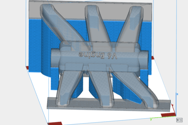
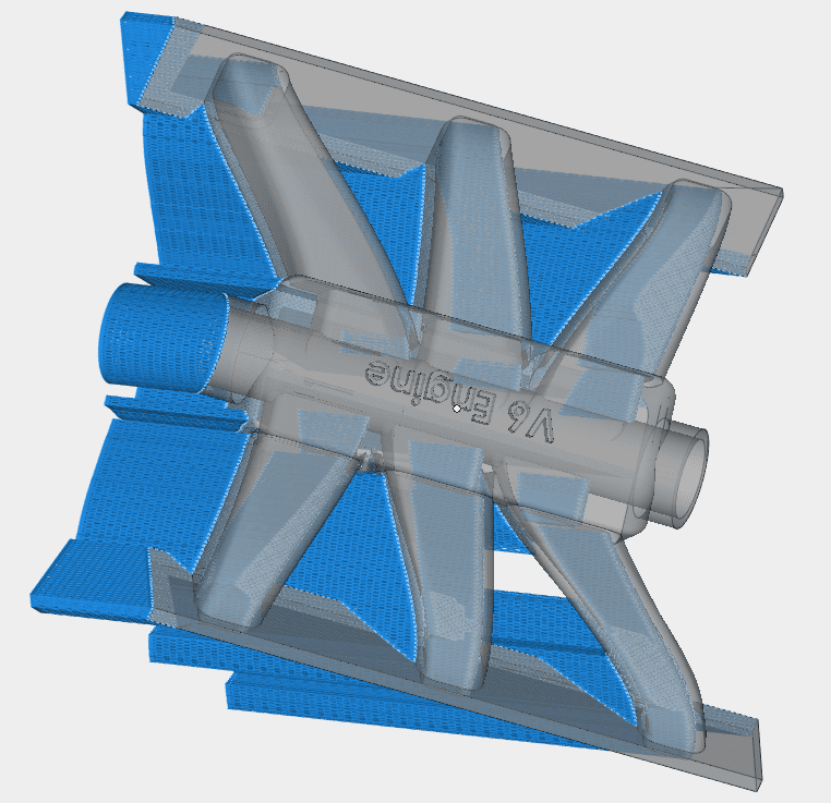
Before Support Optimization:
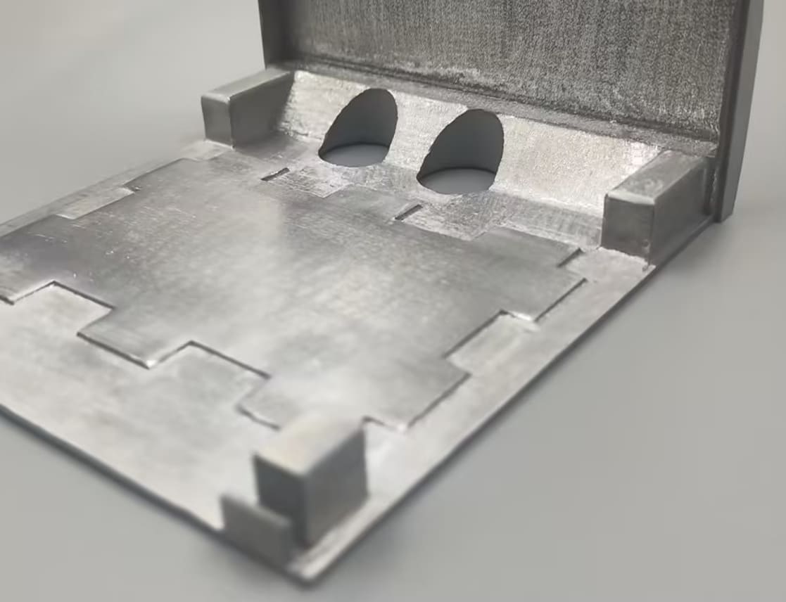
After Support Optimization:
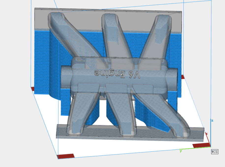
Image Copyright © 3DSPRO. All rights reserved.
Support Optimization Starts with the Geometry and Risk of Each Region
Different areas of an SLM tubular component have different forming risks. Curved surfaces, branches, transition areas, large overhangs, thin walls, and critical interfaces do not require the same level of support.
A uniform, densely packed support structure may improve forming reliability, but it can also introduce large amounts of redundant material. A more effective approach is to divide the component into regions according to overhang angle, unsupported height, wall thickness, and stress distribution.
High-risk areas should receive sufficient support to prevent deformation and forming defects. Lower-risk areas should use less support, while structurally stable areas can be left unsupported. The basic principle is that high-risk areas need support, low-risk areas need less support, and areas without a clear support function should not be unnecessarily supported.
Use Lightweight Supports Instead of Solid Support Structures
Traditional heavy or solid supports provide strong mechanical restraint and heat conduction, but they can significantly increase support volume and make removal more difficult.
For tubular components, support structures can be replaced with lighter designs, including sparse, open, point-based, or line-based structures. These structures are intended to retain the mechanical and thermal functions required during printing while reducing unnecessary support volume.
Lightweight support is particularly important for thin-walled components. Excessively heavy supports can increase local heat accumulation and create stronger bonding between the support and the part. By reducing support volume while maintaining adequate stiffness and heat conduction, both material consumption and post-processing requirements can be reduced.
Design Supports for Easy Removal and Minimal Part Damage
Support optimization should also consider what happens after printing. Tubular components often have thin walls, curved surfaces, and enclosed cavities that make support removal difficult.
The contact area between the support and the component should therefore be minimized where possible. The support root can be adjusted through its cross-sectional thickness and geometry so that it provides sufficient stability during printing while remaining easier to break away during post-processing. This reduces the risk of wall deformation, edge damage, and scratches during support removal.
Internal cavities require additional attention. For enclosed or deep areas that are difficult to access, fine and easy-to-remove supports should be used instead of dense structures. This helps reduce support residue and avoids creating areas that are difficult or impossible to clean after printing.
Match Support Density and Height to Local Forming Conditions
Support density should change according to the local forming conditions rather than remain constant across the entire component.
Stress-concentrated areas and large unsupported regions may require increased support density, while ordinary curved surfaces and regions with better structural stability can use a lower density. This approach provides additional support where it has the greatest functional value and removes redundant support from lower-risk areas.
Support height should also match the actual unsupported height of the structure. Excessively high or redundant support stacking increases printed volume without necessarily improving forming stability. Adjusting support height to the local geometry helps reduce unnecessary material and printing time.
Overhang angle can also be used as one of the criteria for support zoning. For tubular curved surfaces with an overhang angle greater than 45°, support can be significantly reduced in lower-risk regions. For branches, curved sections, and cantilevered areas with more critical overhang conditions, lightweight point-based supports can be introduced to prevent collapse.
Optimize Supports Around Thin Walls and Critical Interfaces
Thin walls require special attention because they have limited thermal capacity and are more susceptible to local heat accumulation and deformation.
For tubular walls with a thickness of 3 mm or less, heavy solid supports should be avoided. Sparse and lightweight support structures can provide the required mechanical and thermal functions while reducing excessive heat accumulation and overly strong bonding between the support and the thin wall.
Critical dimensional features require a different strategy. Tube openings, flanges, assembly surfaces, and other important reference areas should retain an appropriate amount of rigid support to maintain dimensional accuracy. Removing too much support from these areas can lead to deformation of critical interfaces and affect final assembly.
Support optimization is therefore not simply about reducing support everywhere. Different structural requirements must be considered together.
Use Thermal and Process Simulation to Optimize Support Placement
Support placement can be further optimized by analyzing thermal and stress behavior before printing.
Temperature-field and stress-field simulations can identify thermal concentration zones and areas where thin walls are more likely to experience stress concentration. Additional support can then be concentrated in these specific locations instead of applying dense support uniformly over a large surface.
This approach allows support to be matched more precisely to the thermal and mechanical behavior of the component. Rather than relying on large areas of conventional support, targeted reinforcement can be used to stabilize the temperature field and control deformation with less overall support.
Coordinate Support Design with SLM Process Parameters
Support structures should be optimized together with the SLM process parameters used to build the component. A lightweight support structure must still provide adequate mechanical restraint and heat conduction during the printing process.
Important parameters include laser power, scanning speed, and layer thickness. Support geometry and process parameters need to be matched so that lightweight structures remain stable and continue to perform their intended mechanical and thermal functions.
It means support optimization is not an isolated geometric adjustment. It is part of the overall SLM process and should be evaluated together with the selected processing conditions.
What Can Optimized Supports Improve?
A properly optimized support strategy can improve part quality while reducing material, labor, and production time.
Part Quality
Optimized support structures can prevent collapse, excessive dross, cracking, and uncontrolled deformation. They can also reduce support residue, grinding damage, and other post-processing defects. Tube opening roundness, surface profile, and assembly accuracy can therefore be better controlled.
Material and Post-Processing Costs
Reducing redundant support can significantly lower support material consumption. In the engineering results described, optimized support structures reduced overall support weight by 60–80%. At the same time, post-processing grinding time was reduced by more than 35%, lowering labor requirements and finishing costs.
Production Time
Removing redundant support also reduces laser scanning paths and unnecessary support stacking. The resulting optimization increased equipment printing efficiency by more than 20%, while faster post-processing further shortened the overall production cycle.
Production Consistency
Once regional support placement and lightweight support structures are standardized, the process becomes less dependent on individual operator experience. More consistent support strategies can improve repeatability and stabilize part quality in batch production.
Support optimization for SLM tubular components is a process of matching support structures to the actual mechanical, thermal, and dimensional requirements of each region. Effective optimization combines regional support placement, lightweight structures, easy-to-remove connections, appropriate support density and height, thin-wall protection, critical-interface support, thermal and stress analysis, and coordination with SLM process parameters.
The goal is not to minimize support at any cost. It is to eliminate redundant support while preserving the support functions required for stable forming and dimensional control. With the right strategy, tubular components can achieve a better balance of quality, material consumption, post-processing effort, production time, and manufacturing cost.
 0
0