English
 日本語
 Deutsch


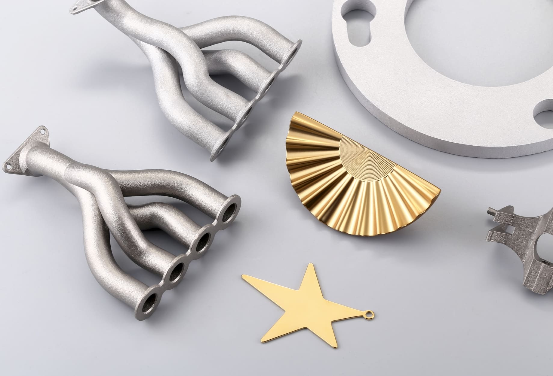
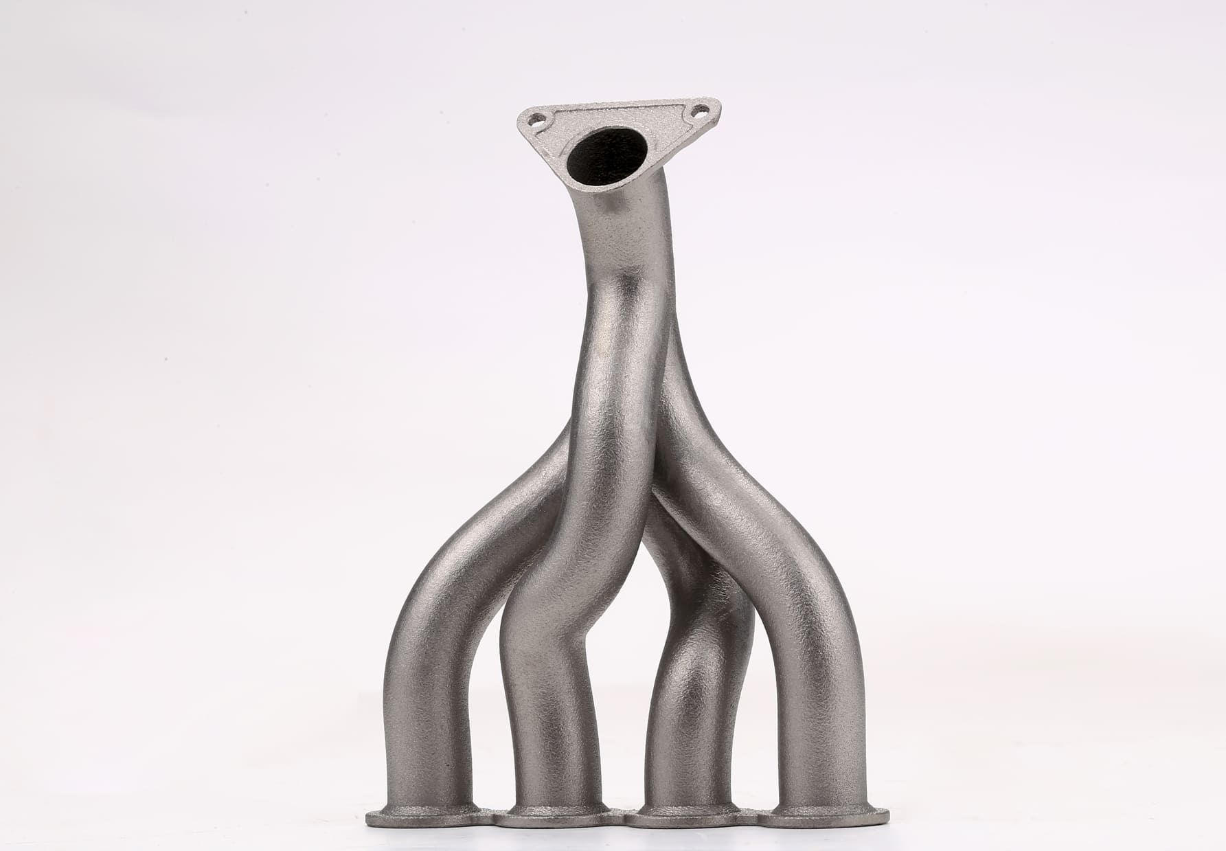
Metal 3D printing can produce complex components with internal channels and consolidated features, but internal porosity remains an important quality concern in laser powder bed fusion (LPBF), including processes commonly called selective laser melting (SLM). Pores reduce the effective load-bearing area and may become crack-initiation sites, particularly under cyclic loading. Their effects depend on size, shape, location, orientation, and the component’s application.
Lack of fusion, keyhole porosity, and gas pores are three common defect types, but they form through different mechanisms. Understanding those mechanisms helps manufacturers choose appropriate process controls and inspection methods instead of changing laser settings blindly. These distinctions are also central to research on metal additive manufacturing porosity.
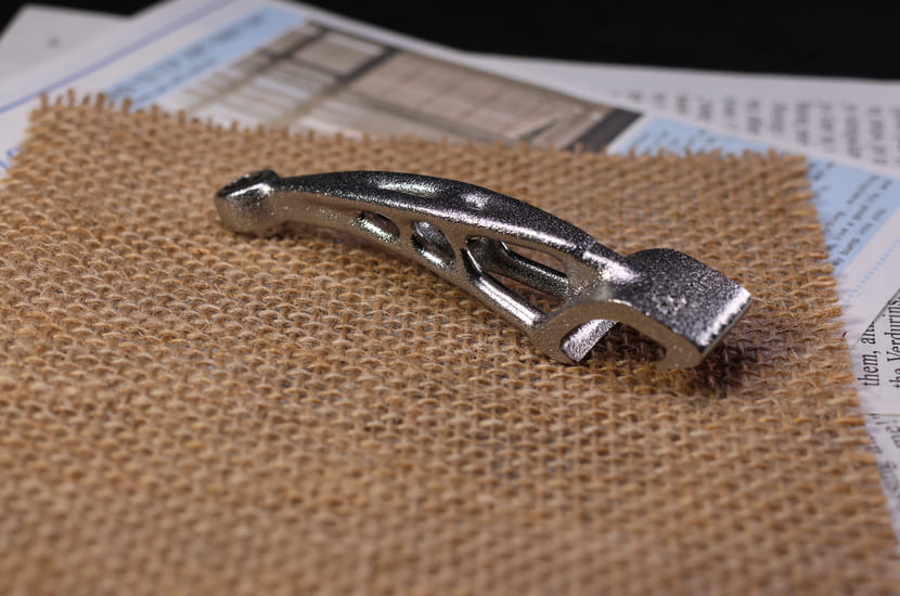
Image Copyright © 3DSPRO. All rights reserved.
Porosity in Metal 3D Printing
In LPBF, a laser scans across a thin layer of metal powder, melting selected regions to form tracks that bond to neighboring tracks and previous layers. The process repeats until the component is built. Porosity can form when the melt pool fails to fuse material fully, becomes unstable, or traps gas during rapid solidification.
The distinction matters because low effective energy input can promote lack of fusion, while excessive or unstable energy input can promote keyhole porosity. Gas pores may originate from gas in the feedstock, gas retained in the melt pool, or gas released during processing. These mechanisms can overlap, and more than one type of pore may appear in the same part.
Porosity is not merely a cosmetic issue. Depending on its location and morphology, it can reduce tensile performance, fatigue life, pressure tightness, and reliability. A single overall density value may therefore be insufficient for safety-critical or highly loaded components.
Three Common Metal 3D Printing Defects
1. Lack of Fusion (LOF)
Lack of fusion occurs when adjacent melt tracks or successive layers do not bond completely. This can leave irregular gaps between solidified regions. Common contributors include insufficient laser energy, excessive scan speed, overly wide hatch spacing, excessive layer thickness, or inconsistent powder spreading. Poorly flowing powder and surface contamination can also interfere with uniform melting.
LOF pores are often irregular, elongated, or relatively flat, and may follow track or layer boundaries. Their shape can make them particularly harmful under cyclic loading because sharp edges and weakly bonded interfaces can concentrate stress and encourage crack growth.
Reducing LOF requires a validated combination of laser power, scan speed, hatch spacing, layer thickness, and scan strategy, not simply increasing power. Powder-bed consistency and recoating quality also matter. Too much energy may solve one problem while introducing another, so parameter changes should be assessed together.
2. Keyhole Porosity
At high power density, the laser can vaporize metal and create a deep, narrow depression in the melt pool known as a keyhole. Vapor pressure helps maintain this cavity. If the keyhole fluctuates or collapses before the metal solidifies, a void can become trapped inside the part.
Keyhole pores are often rounded, but their shape varies with process conditions. They are associated with unstable or excessive local energy input, including some combinations of high laser power and scan speed. The precise process window depends on the alloy, machine, beam characteristics, layer thickness, and scan strategy.
To reduce keyhole porosity, manufacturers need to keep the melt pool within a stable processing window. This may involve adjusting laser power and scan speed, validating the scan strategy, and using qualified parameter sets for the specific material and machine. Monitoring systems can help identify process anomalies, but a signal alone does not confirm a particular pore type.
3. Gas Pores
Gas pores form when gas becomes trapped during melting and solidification. Gas may be present inside powder particles, become entrained in the melt pool, or arise from dissolved gases and reactions involving contaminants. Feedstock handling, powder condition, and chamber atmosphere can influence the risk.
Gas pores are often small and approximately spherical because surface tension tends to minimize the surface area of a void. However, their appearance can overlap with keyhole pores. Shape alone is not enough to determine the origin reliably.
Prevention focuses on qualified powder, appropriate storage and handling, clean process conditions, and the specified build-chamber atmosphere. Reused powder should be managed according to material- and machine-specific procedures. These controls reduce risk but do not guarantee that every pore will be eliminated.
Lack of Fusion vs. Keyhole Porosity vs. Gas Pores
|
Factor |
Lack of Fusion |
Keyhole Porosity |
Gas Pores |
|
Formation mechanism |
Incomplete melting or overlap between tracks or layers |
Collapse or instability of a vapor depression |
Gas trapped during melting or solidification |
|
Typical appearance |
Often irregular, elongated, or flat |
Often rounded; morphology varies |
Often small and spherical |
|
Common contributing factors |
Low effective energy input, wide hatch spacing, poor powder spreading |
Excessive or unstable local energy input |
Gas in powder, entrainment, dissolved gas, or contamination |
|
Main control strategy |
Improve fusion and track overlap; maintain powder-bed consistency |
Stabilize melt-pool behavior and validate parameters |
Control feedstock, atmosphere, and handling |
|
Key caution |
May form along weak interfaces |
Increasing power can worsen the defect |
Shape alone may not identify the source |
How to Detect and Reduce Porosity in Metal 3D Printed Parts
X-ray computed tomography (CT) can reveal the location, size, and distribution of internal voids in three dimensions. Its effectiveness depends on part geometry, material, scan settings, and voxel resolution; defects smaller than the system can resolve may be missed. CT is valuable for complex internal features but may not be practical for every production part.
Metallographic sectioning allows close examination of pores and microstructure on a prepared cross-section. It can help distinguish irregular lack-of-fusion defects from more rounded pores, but it is destructive and only examines the selected plane. Density measurements provide an overall indication of porosity, yet do not show where individual defects are located. In-situ monitoring can flag unusual melt-pool or layer behavior, but suspected anomalies should be correlated with validated inspection methods.
Defect prevention begins before printing. Use qualified powder and follow requirements for storage, handling, sieving, reuse, and chamber atmosphere. Keep the recoater and build surface in good condition, and use processing parameters validated for the alloy and machine. When defects recur, change parameters systematically and document the result rather than relying on a single energy-density number.
Post-processing may help in selected cases. Hot isostatic pressing (HIP), for example, can reduce some internal porosity under suitable material and process conditions. It is not a universal fix: effectiveness depends on defect type, connectivity, component geometry, and the qualified treatment cycle. HIP does not replace process control, required inspection, or acceptance criteria.
The most effective approach is to identify the likely defect mechanism, select a suitable inspection method, and verify corrective actions against the part's engineering requirements. For metal 3D printed components, reliable quality comes from the combination of controlled feedstock, validated process parameters, appropriate post-processing, and inspection matched to the application.
 0


COMMENTS
- Be the first to share your thoughts!