English
 日本語
 Deutsch


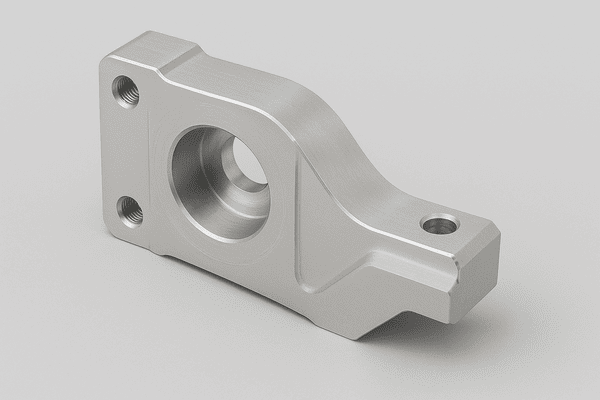
A 3D CAD model is often the starting point for CNC machining. It shows a part’s shape and features, giving the manufacturer geometry for programming and production planning. However, it may not communicate every requirement needed to make and inspect the part as intended. A 2D technical drawing adds dimensions, tolerances, datum references, thread details, surface requirements, and manufacturing notes. Together, the files give the customer and supplier a shared definition of the finished component.
2D Drawings and 3D CAD Models Serve Different Purposes
A 3D CAD model and a 2D technical drawing are complementary documents. They each convey different information in the context of CNC machining.
3D CAD models define the part geometry. They represent the part as a 3D object which makes it much easier to understand complex profiles, pockets, slots, curved surfaces and the relationships between features. The manufacturer can use compatible CAD data (e.g. a STEP file) as the geometric basis for CAM programming and toolpath generation. A 3D model is particularly useful when a part cannot be properly understood from a few flat views.
2D drawings communicate the technical requirements. The ortho views show the part from the required directions. Sectional and detail views are used to show internal features or small areas which would be difficult to read at the overall scale. Dimensions and tolerance callouts will specify the size required and the allowable variation. Notes can be used to specify the material, threads, surface finish, coatings, deburring etc.
For instance, a model may show a hole and the drawing will specify the diameter, depth, location tolerance and thread requirement. The drawing can also specify how flat or parallel two faces have to be.
In some product definition digital workflows, the dimensions and the product manufacturing information are actually built directly into the 3D model. A 2D drawing is still a very useful reference in many CNC quoting, production and inspection situations. The model and the drawing have to agree and have to define the part unambiguously.
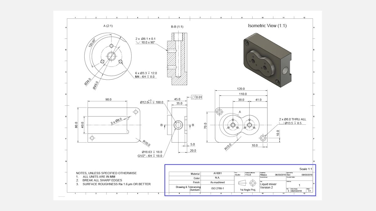
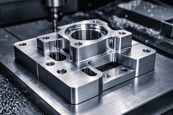
Image Source: Protolabs Network
How 2D Drawings Support CNC Machining Accuracy and Quality
1. Defining Critical Dimensions and Tolerances
A drawing identifies dimensions that control fit and function, such as overall size, hole diameters, slot widths, wall thicknesses, and feature spacing. Tolerances show how far an actual measurement may vary from its nominal value. Not every dimension needs a tight tolerance. Identifying critical dimensions helps the manufacturer choose suitable machining and inspection methods without applying unnecessary precision to non-critical features.
2. Communicating Geometric Dimensioning and Tolerancing (GD&T)
Some manufacturing requirements concern the relationship between surfaces and features, not just their individual sizes. GD&T provides a standardized way to communicate these requirements through datum references and geometric tolerance symbols. For example, flatness controls surface variation, parallelism controls the relationship between two features, perpendicularity specifies a 90-degree relationship, and position controls the location of holes relative to datums. These controls are important for components that must align or mate with other parts. A part can meet its basic dimensions yet still fail to assemble if these relationships are not controlled.
3. Clarifying Holes, Threads, and Machining Feature
A drawing can specify whether a hole is blind or through, its diameter and depth, and whether it requires a thread, counterbore, or countersink. Thread callouts should identify the thread standard, nominal size, pitch where relevant, and thread depth. This helps prevent errors such as machining a clearance hole instead of a tapped hole. Define chamfers, radii, and edge breaks when they affect assembly, safety, or function. Detail views can clarify small features.
4. Specifying Material and Surface Requirements
The drawing or associated technical documentation should identify the material grade and, where relevant, its condition or temper. It should also state required surface roughness and post-processing, such as anodizing, plating, coating, or heat treatment. These specifications affect production and finishing decisions. Distinguish functional surfaces from cosmetic ones and identify where deburring or sharp-edge removal is required instead of assuming every surface needs the same finish.
5. Establishing Inspection and Acceptance Criteria
A drawing gives inspectors measurable requirements: critical dimensions, geometric relationships, and specified surface finishes. Datum references help define how a part should be set up for measurement. When both parties evaluate the component against the same drawing revision, acceptance depends less on subjective interpretation.
Common Problems Caused by Missing or Incomplete 2D Drawings
When an order includes only a 3D model, the supplier may need more information before confirming a quotation or starting production. Missing dimensions, tolerances, material, or finishing requirements can delay technical review.
Incomplete documentation can also force the supplier to make assumptions: whether a hole is intended for a fastener, whether an edge needs a chamfer, or which surfaces require a particular finish. A different interpretation can lead to rework even when the available model has been followed.
Unclear tolerances can also increase costs. A supplier may apply a tighter tolerance than necessary, adding machining and inspection time, or fail to control a critical fit adequately. Missing inspection criteria can then cause delivery disputes: the customer may expect a particular hole position, flatness, or surface condition that was never documented. Clear drawings record these expectations before production.
Essential Information to Include in a CNC Machining Drawing
Before submitting a CNC project, check that the drawing includes the relevant information:
|
Information |
Details to Include |
|
Part Identification |
Part name, part number, drawing revision |
|
Units and Projection |
Millimeters or inches; projection method |
|
Views |
Front, top, side, sectional, and detail views as needed |
|
Material |
Material grade and condition or temper, if applicable |
|
Dimensions |
Overall dimensions and dimensions of critical features |
|
Tolerances |
General tolerances and specific dimensional tolerances |
|
GD&T |
Datum references and geometric tolerances where required |
|
Holes and Threads |
Hole diameter, depth, thread size, pitch, and depth |
|
Surface Requirements |
Surface roughness, coating, plating, or other finishes |
|
General Notes |
Deburring, edge breaks, heat treatment, and special |
Keep the drawing consistent with the latest 3D CAD model and make sure both show the same revision. Avoid conflicting duplicate dimensions, and never rely on scaling the drawing for critical measurements. Mark functional features clearly and state which document takes precedence if the model and drawing differ. Resolve discrepancies with the manufacturer before production.
A 3D CAD model provides the geometry needed to understand and program a CNC-machined part, while a 2D technical drawing communicates the dimensions, tolerances, material, finishing, and inspection requirements that define an acceptable result. Together, they help translate design intent into clear manufacturing instructions.
For more predictable CNC machining, provide a current 3D model alongside a complete 2D drawing whenever the part has critical dimensions, assembly requirements, or specific finishing and inspection needs. At 3DSPRO, submitting both files helps the team review your requirements and assess the project more accurately before production.
 0


COMMENTS
- Be the first to share your thoughts!