 English
  日本語
日本語  Deutsch


Print-in-Place 3D printing allows moving mechanisms to be produced as a single assembled part. Hinges, gears, ball joints, articulated links, and other mechanisms can often be printed without separate pins, fasteners, or manual assembly. This makes Print-in-Place especially useful for prototypes and functional parts with multiple interconnected components.
However, printing a mechanism as one piece does not automatically mean that it will move properly. A design may come out of the printer technically complete but still have joints that are fused, too tight, too loose, or blocked by residual material. Post-processing can create another set of problems by changing the clearance between moving surfaces.
Understanding these limitations is important when designing reliable 3D printed moving parts.
What Makes Print-in-Place 3D Printed Moving Parts Different
The main difference between Print-in-Place and conventional 3D printed assemblies is that the moving components are manufactured in their final relative positions. A hinge, for example, can contain a rotating barrel and pin-like structure that are printed together, even though they are not physically connected by a separately inserted pin.
Print-in-Place eliminates assembly steps, but it also places greater importance on the space between components. The moving surfaces must remain separate enough to move while staying close enough to provide the desired mechanical behavior.
Common Print-in-Place moving structures include:
✅ Hinges and rotating joints
✅Gears and gear trains
✅Ball-and-socket joints
✅Articulated chains and links
✅Snap-fit mechanisms
For these parts, successful printing depends on more than dimensional accuracy. The printing process must also preserve the designed clearance and allow unwanted material to be removed from the moving areas.
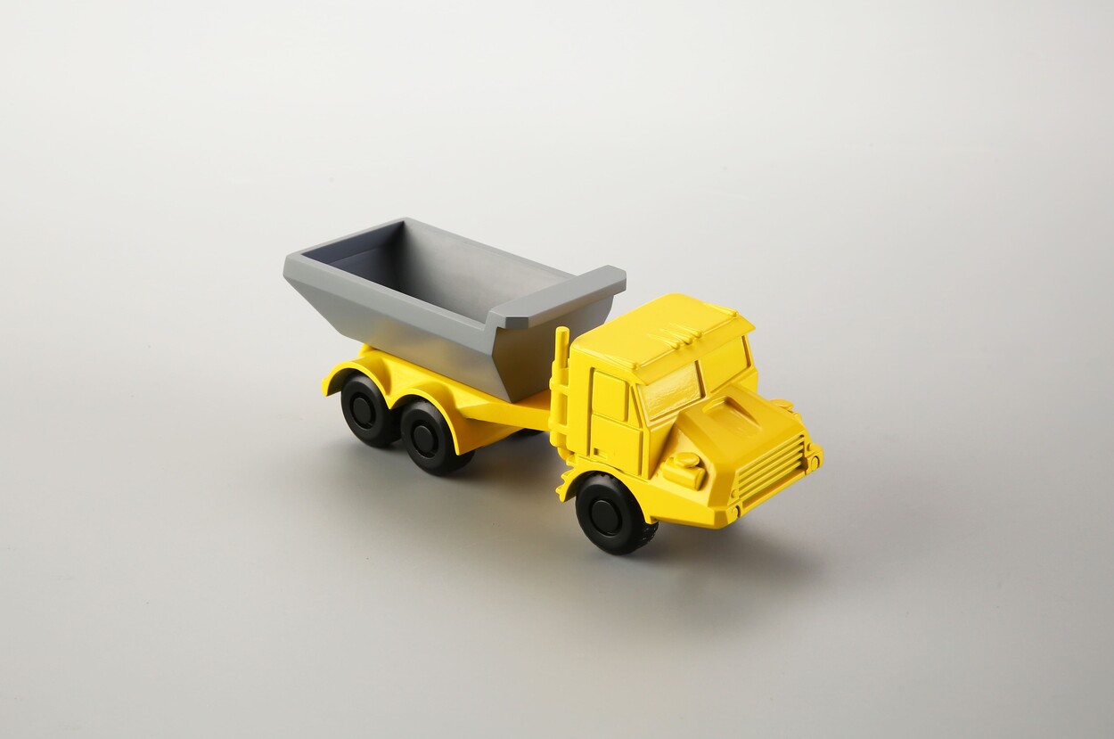
Image Copyright © 3DSPRO. All rights reserved.
Common Clearance Problems in 3D Printed Moving Parts
Clearance is one of the most important design considerations for Print-in-Place mechanisms. It is the intentional space between surfaces that need to move relative to each other.
Clearance That Is Too Small
The most common problem is insufficient clearance. When two surfaces are designed too close together, they may fuse during printing or become difficult to separate afterward. The risk can increase when the design contains fine features, narrow gaps, complex internal geometry, or surfaces that accumulate resin, powder, or other printing residue. A joint that technically has a gap in the CAD model may therefore have little or no usable clearance in the finished part.
Clearance That Is Too Large
Increasing the gap is not always the solution. Excessive clearance can produce loose joints, unwanted play, poor positioning, and reduced mechanical stability. For example, a gear mechanism with excessive space between teeth may have visible backlash, while a loose hinge may wobble instead of rotating smoothly.
Post-Processing Can Affect How Moving Parts Work
A Print-in-Place mechanism does not stop changing once it leaves the printer. Cleaning and surface finishing can significantly affect how its moving components interact.
For resin-based printing, uncured resin can remain in small joints or internal cavities if the part is not cleaned thoroughly. Once cured, this residue can restrict movement or effectively lock components together.
Powder-based processes such as SLS and MJF create a different challenge. Loose powder can become trapped inside enclosed hinges, gears, ball joints, and other mechanisms. Internal channels and gaps therefore need to be designed so that excess powder can be removed.
Surface finishing introduces additional considerations. Sanding and polishing can alter the dimensions of mating surfaces, potentially improving movement in some cases but damaging a mechanism when too much material is removed. Coatings and plating are especially important because they add material to the surface. Painting, powder coating, and electroplating can reduce the original clearance between moving parts. A mechanism that worked before finishing may become stiff or completely stuck afterward.
For this reason, Print-in-Place mechanisms should be designed for their final finished condition, not only for their as-printed dimensions. When a particular finishing process is required, its effect on the moving clearance should be considered during the design stage.
Common Failure Modes of Print-in-Place Moving Parts
|
Failure Mode |
Likely Cause |
Possible Solution |
|
Joint does not move |
Clearance is too small |
Increase the designed clearance |
|
Components are fused |
Insufficient gap or printing residue |
Adjust the gap and improve cleaning |
|
Joint is too loose |
Excessive clearance |
Reduce the gap based on testing |
|
Movement is rough |
Surface defects or residual material |
Improve printing conditions or finishing |
|
Internal mechanism is blocked |
Powder, resin, or support material remains inside |
Improve access and material removal |
|
Joint works before finishing but not afterward |
Coating or plating reduces clearance |
Account for finishing thickness |
A particularly important issue is the difference between printing successfully and functioning successfully. A model may have no visible printing defects and still fail as a mechanism.
The first movement test is therefore important. For some parts, the joint may need to be carefully freed after cleaning or powder removal. However, excessive force should be avoided because thin hinges, gears, or articulated links can break during this step.
If a mechanism is critical to the final application, producing a small test piece first can be more efficient than modifying an expensive full-size part after failure.
When Print-in-Place Is Not the Best Choice
Print-in-Place is highly convenient, but it is not suitable for every moving mechanism.
Separate assembly may be a better option when the application requires extremely tight tolerances, high mechanical loads, replaceable wear components, or highly controlled bearing surfaces. A conventional assembly with separate pins, bearings, shafts, or fasteners can provide more precise control over these components.
Print-in-Place can also become less practical when the mechanism requires extensive post-processing. If an internal joint is difficult to clean, sand, polish, coat, or inspect, maintaining consistent movement may be challenging.
The same consideration applies to large production quantities. Although Print-in-Place reduces assembly work, a separately assembled design may sometimes offer better repeatability or serviceability for long-term production.
The best approach is therefore to match the mechanism to the manufacturing process. Print-in-Place works especially well when reducing assembly complexity is important and the moving geometry can be designed with sufficient clearance and accessible internal spaces.
 0
0


COMMENTS
- Be the first to share your thoughts!