English
 日本語
 Deutsch


Metal 3D printing can produce shapes that are difficult to machine or form conventionally. However, a part that can be printed as one piece is not always easy to finish. Narrow openings, tapered cavities, and enclosed internal surfaces can make supports difficult to reach after printing. Tools may not pass through the opening or reach support attachment points without damaging the part.
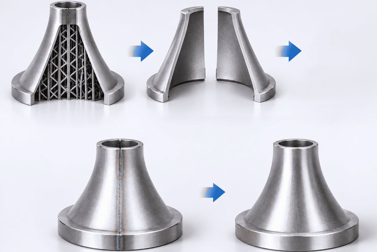
One solution is to plan for assembly rather than insist on a one-piece build. A component can be divided into sections, printed separately, and cleaned while its internal surfaces are accessible. The sections are then welded together to create the complete part.
Typical Metal Part Geometries That Make Support Removal Difficult
Cone-shaped, horn-shaped, and funnel-shaped components can create internal support-removal challenges. Their cavities widen or narrow along the part, while the opening for post-processing may remain relatively small. Depending on build orientation, overhanging internal surfaces may require supports deep inside the cavity.
Consider a conical component with a narrow throat and a wider internal chamber. Supports attached to the inner wall or underside of an overhang may be visible from the opening but beyond the reach of cutting tools, grinders, or other equipment. A horn-shaped component can present a similar problem when its curved internal profile prevents tools from reaching support contact points.
Other examples include intersecting channels, recessed chambers, curved ducts, and partially enclosed cavities. Even if a part prints successfully, inaccessible supports may remain inside, restrict internal clearance or flow, and prevent the component from meeting its functional or finishing requirements. The design challenge is not only whether a geometry can be printed, but whether its temporary structures can be removed afterward.
AI Generated Image
Splitting the Design to Improve Manufacturability
When support access is the main obstacle, dividing the original model into sections can make it easier to manufacture. Rather than printing a closed cavity as one piece, the designer creates separate components with internal surfaces exposed during post-processing.
Choose the split position according to the cavity shape, support locations, functional features, and welding process. For a cone- or horn-shaped part, a longitudinal split can open the internal profile and expose supports along the inner wall. A transverse split may work better when the inaccessible area is concentrated in one section. The suitable direction depends on the geometry.
The joining interface must also be planned before printing. The sections need mating surfaces, access for weld preparation, and features or reference surfaces for alignment. Consider machining allowance, weld location, and whether the final seam could affect appearance, sealing, strength, or another functional requirement.
Printing Separate Sections and Removing Internal Supports
After splitting the model, each section can be oriented and built separately using a suitable metal 3D printing process, such as laser powder bed fusion. Evaluate each orientation for support demand, build stability, surface quality, and accuracy. Splitting does not necessarily eliminate supports; it makes them more accessible.
After printing and build-plate removal, operators can reach support contact points directly and use suitable cutting, grinding, or machining methods without working through a narrow opening. Loose powder and other residues should also be removed from the cavities before joining.
Inspect the internal surfaces to confirm that supports have been removed from the required areas and that thin walls or critical features have not been damaged. Correcting an internal issue is easier before welding closes the assembly. Finally, clean and prepare the mating surfaces according to the selected welding procedure.
Reassembling the Printed Sections Through Welding
With internal supports removed, the sections can be aligned to restore the original geometry. Before welding, check the joint gap, orientation, and key dimensions against the requirements. Fixtures, clamps, or locating features can help hold the components in position.
Select the welding process based on the alloy, section thickness, joint design, and service requirements. A material's suitability for metal 3D printing does not mean every printed part can be welded using the same parameters. Material condition, prior heat treatment, wall thickness, and joint accessibility should all be considered when defining the welding procedure.
Welding heat can cause shrinkage and distortion, changing roundness, concentricity, or overall dimensions. A controlled welding sequence, suitable fixturing, and inspection help manage these risks. After welding, the assembly may need grinding, polishing, or machining to meet surface and dimensional requirements. Plan finishing around the component's function, not only the appearance of the weld.
Key Considerations When Combining Metal 3D Printing and Welding
Material and weld compatibility: Confirm that the alloy and its post-print condition are suitable for the proposed welding method. Some materials require tighter heat-input control or specific procedures to reduce cracking risks.
Split location and joint design: Place the seam where it can be welded and inspected without compromising critical surfaces or functions. The joint should support reliable fit-up and provide adequate welding access.
Dimensional control: Account for printing tolerances, machining allowance, weld shrinkage, and distortion. Critical dimensions may need machining after welding.
Internal cleanliness and inspection: Remove supports, loose powder, and residues before assembly. Define how the internal cavity and weld will be inspected, particularly for parts with sealing, pressure, flow, or safety requirements.
Post-weld finishing and treatment: Determine whether stress relief, heat treatment, machining, polishing, or surface finishing is needed. The sequence depends on the alloy, printing process, welding procedure, and application.
When Should You Consider Split Printing and Welding?
Split printing and welding can be a practical solution for metal components with complex internal geometries. Consider this approach in the following situations:
✅ Inaccessible Internal Supports: The part has enclosed, tapered, or narrow internal cavities where supports cannot be fully removed through existing openings.
✅ Complex Internal Geometries: The component features cone-shaped, horn-shaped, or funnel-shaped structures that restrict access to internal surfaces.
✅ Limited Support Removal Access: Conventional tools cannot reach internal support attachment points without risking damage to thin walls or delicate features.
✅ Unsuccessful Design Optimization: Changing the build orientation or modifying the support structure cannot adequately solve the support removal challenge.
✅ Weld-Compatible Materials: The selected metal alloy and component design are suitable for welding and can meet the required structural and functional performance after assembly.
✅ Benefits Outweigh Additional Processing: The improved access for support removal justifies the additional steps involved in welding, alignment, inspection, and post-weld finishing.
 0


COMMENTS
- Be the first to share your thoughts!