English
 日本語
 Deutsch


Hole machining is a fundamental operation in CNC manufacturing. From mounting holes and threaded connections to precision bearing bores, hole quality directly affects component assembly, alignment, and performance. However, creating a hole that meets a drawing specification involves more than selecting the correct diameter. Dimensional accuracy, roundness, surface finish, and positional accuracy must also be considered.
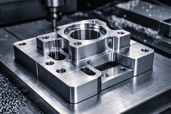
CNC drilling, boring, and reaming are three common hole-machining operations, each serving a different purpose. Understanding their differences helps engineers choose an appropriate process, avoid unnecessary machining steps, and achieve the required precision at a reasonable cost.
CNC Drilling, Boring, and Reaming
CNC Drilling
CNC drilling creates an initial hole by advancing a rotating drill into a workpiece. It is generally the fastest and most economical of the three operations for producing standard holes.
Drilling is commonly used for clearance holes, mounting holes, pilot holes, and holes prepared for tapping or finishing. It works with metals and plastics, although cutting parameters and tooling must be adjusted according to the material.
Drilled holes may exhibit dimensional variation, burrs, taper, or imperfect roundness depending on tool condition, workpiece material, hole depth, and machine rigidity. For general-purpose holes, these characteristics may be acceptable. For precision fits, an additional machining operation may be necessary.
CNC Boring
CNC boring enlarges an existing hole using a single-point cutting tool, typically mounted on a boring bar. By controlling the cutting tool's radial position, boring allows more direct adjustment of the final hole diameter than ordinary drilling.
Boring is particularly useful for larger holes, bearing housings, and components requiring closer control of diameter, roundness, or alignment. It can also improve the geometry of a previously drilled hole when the setup and machining strategy allow the required correction.
However, boring performance depends on tool rigidity and workholding. Long, slender boring bars can deflect or vibrate, especially when machining deep holes, potentially affecting dimensional accuracy and surface finish.
CNC Reaming
CNC reaming is a finishing operation that removes a small amount of material from an existing hole. A reamer uses multiple cutting edges to bring the hole closer to its target diameter and improve surface consistency.
Reaming is commonly used for locating-pin holes, bushings, and other features that require consistent sizing and relatively smooth internal surfaces. The initial hole must already be close to the required dimensions because a reamer is not intended to remove large amounts of material.
Unlike boring, reaming generally follows the existing hole rather than correcting its location. Therefore, accurate positioning and a suitable pre-machined hole are essential.
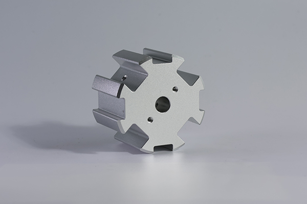
Image Copyright © 3DSPRO. All rights reserved.
Drilling vs. Boring vs. Reaming
|
Factor |
CNC Drilling |
CNC Boring |
CNC Reaming |
|
Primary purpose |
Create an initial hole |
Enlarge and refine an existing hole |
Finish an existing hole |
|
Cutting tool |
Drill bit |
Single-point boring tool |
Multi-edge reamer |
|
Material removal |
Generally higher |
Controlled material removal |
Small finishing allowance |
|
Diameter control |
Suitable for general requirements |
Adjustable for close diameter control |
Consistent final sizing |
|
Geometry control |
Limited compared with finishing operations |
Can improve roundness and alignment |
Primarily follows the existing hole |
|
Surface finish |
Generally moderate |
Can produce a good finish |
Typically improves finish consistency |
|
Typical applications |
Mounting and clearance holes |
Precision bores and bearing housings |
Locating pins and precision fits |
Drilling is generally the preferred starting point when material must be removed efficiently. Boring is appropriate when the hole requires greater control over its diameter or geometry, while reaming is suitable when a properly prepared hole needs more consistent sizing and surface finish.
How to Choose the Right Hole Machining Process
The best process depends on the hole's function and the consequences of dimensional variation.
Choose drilling for standard holes. Clearance holes and general mounting holes often do not require additional finishing. Standard drill sizes can simplify programming and reduce machining time. Avoid specifying tighter tolerances than the assembly actually needs.
Choose boring for precision geometry. Bearing housings, larger bores, and features requiring controlled diameter or alignment may benefit from boring. Because the cutting diameter can be adjusted, boring is useful when the required dimensions cannot be achieved reliably through drilling alone.
Choose reaming for consistent hole sizing. Reaming is a practical option for locating pins, bushings, and other applications that require controlled hole dimensions and improved surface finish. It is most effective when the pre-drilled hole has the correct allowance and adequate positional accuracy.
Some components require multiple operations. For example, a locating hole may be drilled undersize and then reamed to its final diameter. A precision bore may be drilled first and subsequently bored to improve its geometry. Not every hole requires both roughing and finishing, so process selection should reflect actual functional requirements rather than automatically adding operations.
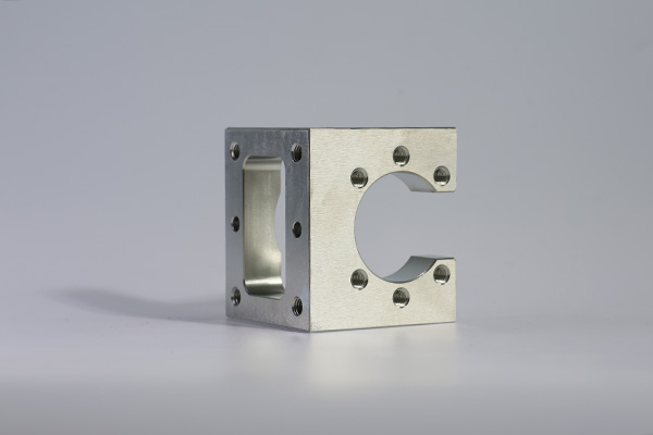
Image Copyright © 3DSPRO. All rights reserved.
Design Guide for CNC Machined Holes
Designing holes for CNC machining requires balancing dimensional accuracy, tool accessibility, surface finish, and manufacturing cost. The following guidelines provide practical starting points for specifying hole features and selecting suitable machining operations.
1. Hole Diameter and Dimensional Tolerances
Whenever possible, use standard drill diameters to reduce tooling requirements and machining costs. For general-purpose holes, conventional drilling is often sufficient, while close-fitting holes may require reaming or boring.
Typical reference values for metal parts are shown below.
|
Requirement |
Typical Reference Value |
Recommended Design Approach |
|
General-purpose drilled hole diameter |
Approximately ±0.03–0.05 mm |
Suitable for many non-critical holes, subject to process capability |
|
Precision reamed hole |
H7 tolerance class is commonly achievable |
Specify H7 only when the assembly requires this level of control |
|
Precision bored hole |
Approximately ±0.005 mm may be achievable in controlled setups |
Confirm capability with the manufacturer before specifying |
|
Standard tooling for small holes |
Approximately 2.5 mm and above |
Smaller holes may require specialized micro-machining |
These ranges are indicative rather than guaranteed process limits. For example, an H7 hole with a nominal diameter of 10 mm has a permissible diameter range of 10.000–10.015 mm. At a nominal diameter of 20 mm, the H7 range is 20.000–20.021 mm. H7 is a hole tolerance class, not a symmetric ± tolerance.
When designing bearing seats, locating-pin holes, or other precision interfaces, specify the required tolerance on the engineering drawing. Avoid applying tight tolerances to every hole, as additional machining and inspection can increase cost without improving functionality.
2. Hole Depth and Geometry
Hole depth directly affects tool rigidity, chip evacuation, and machining time. Deep holes are more difficult to machine accurately because cutting forces, tool deflection, and chip accumulation become increasingly important.
|
Design Parameter |
Recommended Guideline |
Manufacturing Consideration |
|
Preferred drilled-hole depth |
Up to 4 × nominal diameter (4D) |
Generally easier to machine with standard tooling |
|
Deeper drilled holes |
4D–6D |
May require additional attention to chip evacuation and cutting conditions |
|
Holes exceeding 6D |
Special tooling or machining strategies may be required |
Confirm feasibility and cost before finalizing the design |
|
Very deep holes |
Above approximately 10D |
May require dedicated deep-hole drilling processes |
For example, a 6 mm diameter hole has a preferred depth of up to 24 mm at a 4D ratio. A 36 mm deep hole reaches 6D and may require additional manufacturing considerations. These ratios are general design recommendations, not absolute machine limits.
3. Surface Finish and Fit Requirements
Surface roughness should be specified according to the hole's function rather than assigning the same requirement to every feature.
|
Machining Process |
Typical Surface Roughness (Ra) |
Suitable Applications |
|
CNC drilling |
3.2–6.3 µm |
General mounting and clearance holes |
|
CNC reaming |
0.8–1.6 µm |
Locating-pin holes and precision fits |
|
CNC boring |
Approximately 0.4–1.6 µm in suitable conditions |
Precision bores and bearing interfaces |
4. Material and Tool Selection
Different materials respond differently to drilling and finishing operations. Aluminum generally offers good machinability, while stainless steel may require more careful control of cutting conditions and heat. Engineering plastics can deform or change dimensions because of heat, elastic recovery, and residual stress.
For deep holes, choose tools and machining strategies that support effective chip evacuation. For precision bores, ensure that the setup is sufficiently rigid to minimize vibration and tool deflection.
Standard drill diameters are usually preferable when they meet the functional requirements. Non-standard diameters may require alternative tooling or an additional finishing operation, potentially increasing cost and machining time.
5. Allowances for Finishing Operations
Reaming removes only a small amount of material, so the pre-machined hole must leave an appropriate finishing allowance. Too much material can overload the reamer, while too little may prevent it from removing drilling marks consistently.
The following values are preliminary references for total material allowance on the hole diameter.
|
Target Hole Diameter |
Approximate Reaming Allowance |
|
Up to 3 mm |
0.05–0.10 mm |
|
3–6 mm |
0.10–0.15 mm |
|
6–12 mm |
0.15–0.25 mm |
|
12–30 mm |
0.25–0.40 mm |
|
Above 30 mm |
0.40–0.50 mm as a preliminary reference; boring may be more appropriate |
These values are starting points rather than universal requirements. The suitable allowance depends on the reamer design, workpiece material, hole size, and machining conditions. Confirm the pre-ream diameter using the selected tool manufacturer's recommendations.
Precision CNC Hole Machining at 3DSPRO
Selecting the right hole-machining process is essential to producing CNC components that fit and function as intended. Whether a part needs standard mounting holes, precision bearing bores, or consistent locating-pin holes, the manufacturing approach should match its functional and dimensional requirements.
3DSPRO provides custom CNC machining services for components with different geometries, materials, and finishing needs. When preparing a design for quotation, provide an engineering drawing with hole diameters, critical tolerances, hole depths, thread specifications where applicable, and any required surface-finish details.
For particularly demanding features, identify the holes that control assembly or performance so they can receive appropriate attention during manufacturing and inspection.
By matching drilling, boring, and reaming to the requirements of each feature, engineers can balance precision, production efficiency, and cost while improving the reliability of their CNC-machined parts.
 0


COMMENTS
- Be the first to share your thoughts!