 English
  日本語
日本語  Deutsch


Common Fit Types for 3D Printed Parts
Before choosing a clearance, identify the type of fit the parts need.
1. Clearance Fit
A clearance fit leaves intentional space between two mating parts, allowing them to be assembled and separated without excessive force. It is commonly used for removable covers, housings, pins, and parts that do not need to hold each other tightly.
2. Sliding Fit
A sliding fit is designed for parts that need to move linearly along one another. The clearance must be large enough to prevent binding but small enough to limit unwanted movement. Rails, sliders, drawers, and telescoping components are common examples.
3. Rotating Fit
A rotating fit allows one part to rotate around another, such as a shaft inside a hole or a 3D printed hinge. In addition to clearance, designers need to consider roundness, surface roughness, and the amount of play acceptable for the application.
4. Press Fit
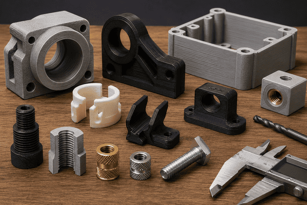
A press fit uses a mating feature that is slightly larger than the receiving feature, so the parts stay together through friction or elastic deformation. It is often used for bearings, pins, bushings, and inserts. Unlike a clearance fit, a press fit does not rely on a free gap between the mating surfaces.
5. Interference Fit
An interference fit intentionally creates overlap between mating dimensions so that the assembled parts remain firmly engaged. It can provide stronger retention than a simple clearance fit, but excessive interference may deform or damage a 3D printed part, especially when the material is brittle.
6. Snap Fit
A snap fit uses a flexible feature, such as a hook, tab, or cantilever arm, to lock two parts together. The design needs enough clearance for the feature to deflect during assembly and enough space to prevent surrounding parts from obstructing that movement. Snap fits are common in housings, lids, clips, and tool-free assemblies.
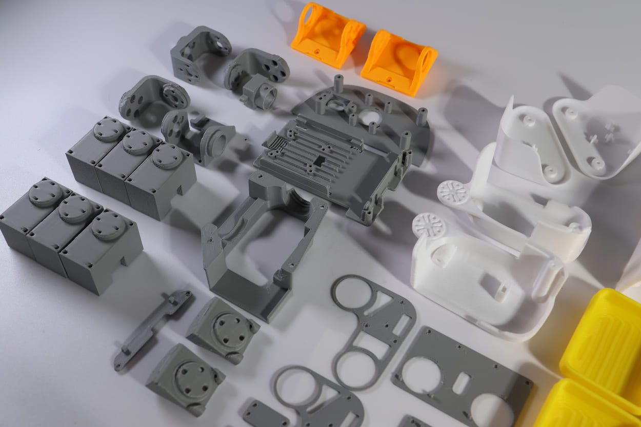
Image Copyright © 3DSPRO. All rights reserved.
Clearance Size References
Clearance should be treated as a starting design value, not a guaranteed production dimension. The following references can help establish an initial design range:
|
Fit or Application |
Starting Clearance Reference |
|
Moving FDM parts |
About 0.3 mm or more |
|
SLA clearance between mating features |
About 0.4 to 0.5 mm |
|
SLS integrated moving assemblies |
About 0.3 to 0.6 mm, depending on feature size |
|
MJF connecting parts |
About 0.4 mm |
|
MJF moving parts |
About 0.7 mm as a general starting point |
|
SLM moving parts |
About 1 mm as a general starting point |
These numbers are not interchangeable across printers, materials, or geometries. For a critical assembly, it is better to validate the design with a small test coupon before committing to the full part.
Typical Clearance Considerations for Different Structures
Shaft and hole assemblies need enough radial clearance for the shaft to enter and move without binding, but excessive clearance creates unwanted play. Hole accuracy and roundness also matter. For a critical bearing seat or precision shaft, printing the hole slightly undersized and machining it afterward may be more reliable than depending entirely on the printed geometry.
Sliding structures need clearance along the entire contact path, not just at the entrance. A slider that fits at one end can still bind because of local warping, surface roughness, or dimensional variation farther along its travel. Long sliding surfaces therefore require more attention to straightness and consistency than short mating features.
Rotating structures need clearance around the shaft or pivot while also controlling unwanted lateral play. The required gap depends on the rotation speed, load, surface finish, and whether the movement is continuous or occasional. A simple hinge that opens occasionally can tolerate a different fit from a functional rotating mechanism.
Snap-fit structures need both assembly clearance and room for elastic deflection. Increasing the gap alone does not solve a snap-fit problem if the arm is too stiff, too short, or collides with another feature during insertion.
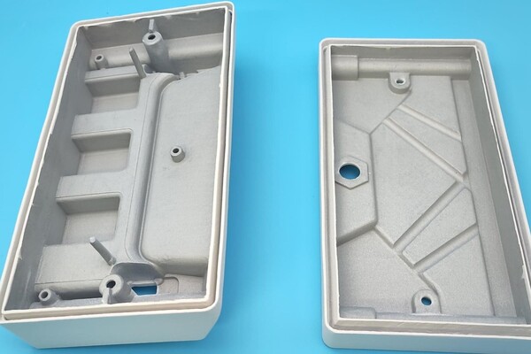
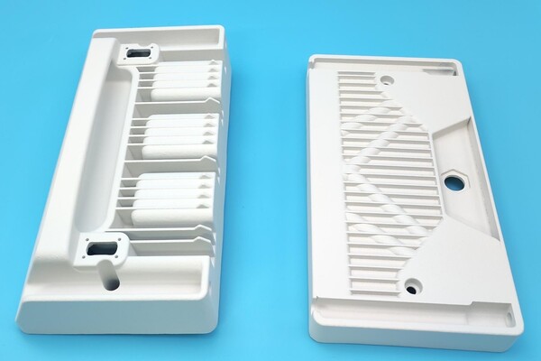
For interlocking parts and enclosures, think about the entire interface. Small deviations across several walls or mating features can accumulate and prevent assembly even when every individual dimension appears reasonable.
3D Printing Process Changes the Clearance You Need
The printing process strongly influences the practical clearance window.
FDM parts can be affected by nozzle size, layer settings, orientation, first-layer effects, and material shrinkage or warping. Material properties, print settings, orientation, and model size can all influence fit.
SLA can produce fine details, but cured resin, support removal, washing, and post-curing can affect mating surfaces. Use process-specific minimum clearance values rather than one universal number for all resin printing.
SLS and MJF avoid filament extrusion, but powder-based processes introduce different considerations. Clearance must allow parts to separate or move and must also provide enough space for powder removal. Larger spacing is needed for moving MJF assemblies.
Metal 3D printing, such as SLM, requires even more careful treatment for precision fits. Thermal effects, surface roughness, support removal, and machining requirements can make a printed-only fit unsuitable for critical interfaces. For these applications, the mating surface may need to be intentionally machined after printing rather than relying on the as-printed dimension.
Post-Processing and Tolerance Stack-Up Can Change the Final Fit
A clearance that works immediately after printing may change after finishing. Sanding and polishing remove material from mating surfaces, while spray painting, powder coating, and electroplating add material. These changes can be small individually but significant for tight-fitting components. Any planned finishing operation should therefore be considered when defining the final fit.
Tolerance stack-up is another common source of assembly problems. If a cover, wall, slot, pin, and hole each vary slightly from their nominal dimensions, those deviations can accumulate in the assembled product. A design that looks correct in CAD may therefore become too tight when several tolerances act in the same direction.
For functional assemblies, the safest workflow is to identify the fit type first, choose a process-appropriate starting clearance, account for material and post-processing, and then validate the result with a representative test piece. The goal is not to find one universal clearance number, but to create enough dimensional margin for the actual manufacturing process while maintaining the required movement, retention, or alignment.
 0
0


COMMENTS
- Be the first to share your thoughts!