 English
  日本語
日本語  Deutsch


One of the greatest advantages of 3D printing is the ability to produce complex internal geometries that are impossible or extremely costly to machine using traditional manufacturing methods. Engineers can integrate cooling channels, airflow passages, hydraulic paths, and lightweight internal structures directly into a single part without assembly.
However, just because a channel can be modeled in CAD does not mean it can be successfully manufactured. Internal passages introduce unique challenges during printing, cleaning, and inspection. Poorly designed channels may become blocked by trapped powder, uncured resin, or support material, making the finished part unusable.
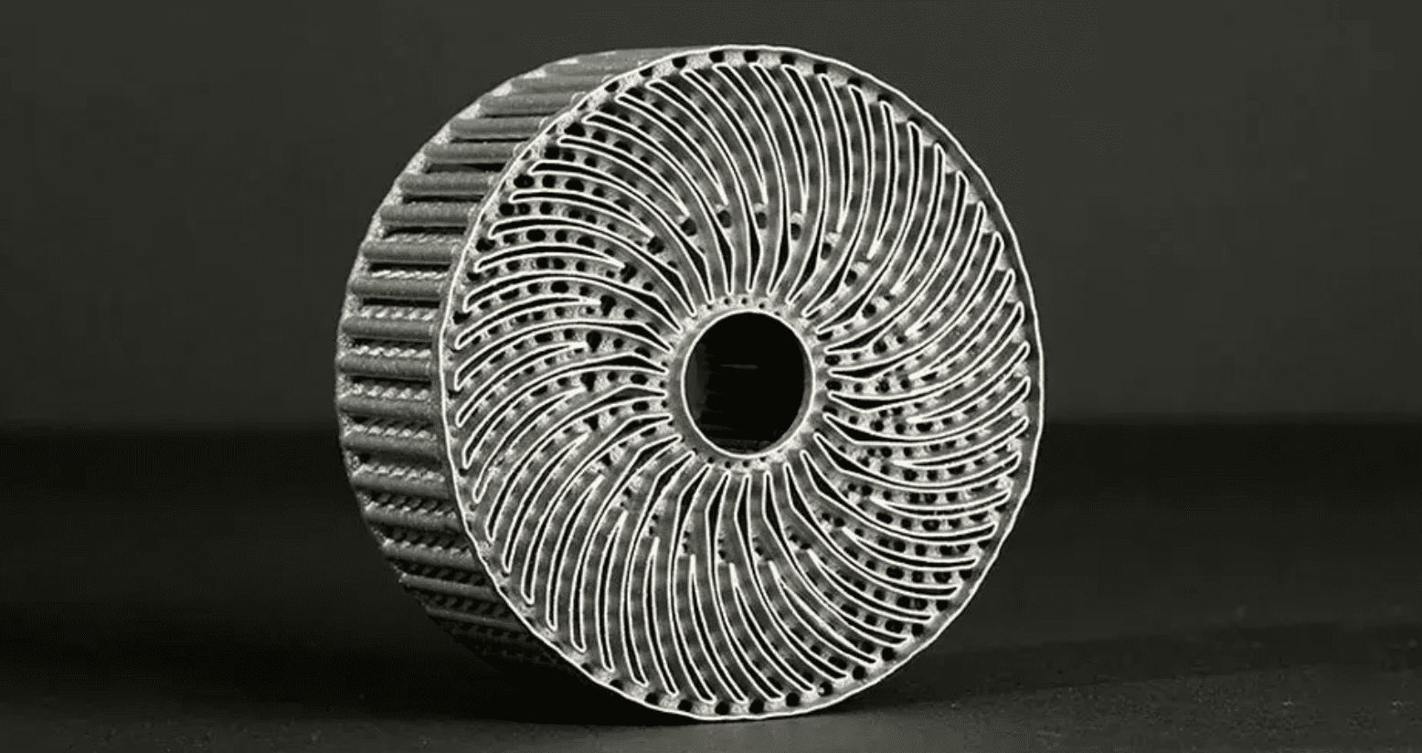
Image Source: 3D Systems
What Are Channels and Internal Passages in 3D Printed Parts?
Internal channels are enclosed pathways built inside a component. Depending on the application, they may transport liquids, gases, compressed air, or simply reduce weight while maintaining structural strength.
Common applications include conformal cooling channels in injection molds, hydraulic and pneumatic manifolds, heat exchangers, medical devices with internal fluid paths, aerospace fuel or air ducts, and lightweight industrial components.
Unlike conventional drilling, which is generally limited to straight holes, 3D printing allows channels to curve, branch, and follow complex geometries. This design freedom improves thermal efficiency, reduces assembly steps, and enables better overall product performance.
Nevertheless, designers must balance the flexibility with manufacturing constraints. Internal features cannot be inspected or repaired easily after printing, so good design practices become especially important.
Design Challenges of Internal Channels
Designing enclosed passages requires more than simply creating a hollow cavity inside a model. Several manufacturing issues can affect print quality and functionality.
Trapped Material
Powder-based technologies such as SLM, SLS, and MJF leave loose powder inside enclosed cavities after printing. If the channel is too small or too long, powder may become trapped permanently. Similarly, SLA and DLP printing leave uncured resin inside internal cavities. Without proper drainage, the resin may cure later, partially blocking the passage.
Unsupported Overhangs
Many internal channels contain curved ceilings that may require support during printing. Since internal supports are often impossible to remove, unsupported surfaces may sag or deform. Designing self-supporting geometries is especially important for metal 3D printing.
Surface Roughness
Compared with machined holes, 3D printed channels typically have rougher internal surfaces. Increased roughness creates additional friction, reducing flow efficiency for liquids or gases. Applications involving high flow rates or precise pressure control should account for this during the design stage.
Inspection Difficulties
Once a part is fully enclosed, inspecting internal features becomes challenging. Industrial CT scanning can verify internal geometry but adds additional cost. Designing channels that are easier to clean and verify reduces manufacturing risks.
Recommended Design Guidelines
Following several fundamental design rules can significantly improve both print success and functional performance.
Choose an Appropriate Channel Diameter
Although every process has different capabilities, larger channels are generally easier to manufacture and clean. Very narrow passages increase the likelihood of trapped powder, resin blockage, incomplete cleaning, and dimensional inaccuracies. When possible, avoid designing channels near the minimum printable feature size specified by your manufacturing service.
Consider Channel Shape
Circular channels work well for many applications, but they are not always the easiest geometry to print. For metal 3D printing, self-supporting shapes such as teardrop or diamond profiles often perform better because they reduce unsupported overhangs inside the channel. These profiles minimize sagging while maintaining similar flow characteristics.
Maintain Adequate Wall Thickness
Channels should not be placed too close to the outer surface of a part. Thin surrounding walls may warp during printing, crack during post-processing, reduce structural strength, and distort under pressure. Maintaining sufficient wall thickness helps preserve dimensional accuracy and mechanical performance.
Avoid Sharp Internal Corners
Sharp turns create two problems simultaneously:
• Increased pressure loss during operation;
• Greater printing difficulty.
Smooth curves and generous bend radii improve fluid flow while also reducing stress concentrations inside the part.
Avoid Extremely Long, Narrow Passages
Even if a narrow channel can technically be printed, cleaning it may be impossible. If a design requires very long internal flow paths, consider dividing the component into multiple sections for assembly after cleaning. The approach often provides higher manufacturing reliability than attempting a single enclosed passage.
Designing for Powder, Resin, or Support Removal
Designing the channel itself is only half the challenge. Engineers must also consider how trapped material will be removed after printing.
Add Powder Escape Holes
For powder-bed fusion processes, escape holes allow loose powder to be evacuated using compressed air or vibration. Without escape holes, powder may remain permanently trapped inside the part, increasing weight and potentially affecting performance. Multiple escape points often improve cleaning efficiency for complex internal networks.
Include Resin Drainage Paths
Resin printing requires sufficient drainage openings for uncured resin to flow out during post-processing. Drain holes should be positioned so gravity naturally assists resin removal during cleaning. Poor drainage can leave sticky resin inside cavities, which may later cure and obstruct the channel.
Minimize Internal Supports
FDM printing frequently relies on support structures for overhangs. Inside enclosed channels, however, supports may be impossible to remove. Whenever possible, redesign the channel geometry to become self-supporting rather than depending on removable supports.
Plan for Cleaning Access
Some industrial components require flushing, ultrasonic cleaning, or compressed-air cleaning before delivery. Providing temporary cleaning ports or removable access plugs can greatly simplify maintenance and quality inspection for complex internal systems.
How Different 3D Printing Technologies Affect Internal Channel Design
|
Technology |
Key Design Considerations for Internal Channels |
|
SLM (Selective Laser Melting) |
Design self-supporting channel shapes such as teardrops to reduce unsupported overhangs. Include sufficient powder escape holes, especially for enclosed cavities. Larger channel diameters improve powder removal. |
|
SLS (Selective Laser Sintering) |
Unsintered nylon powder must be removed from internal passages. Avoid long, narrow channels that are difficult to clean. Multiple cleaning openings may be required. |
|
MJF (Multi Jet Fusion) |
Similar to SLS, internal powder removal is critical. MJF generally provides excellent dimensional consistency, but channels still require adequate size for complete cleaning. |
|
SLA / DLP / LCD |
Internal cavities should include drainage holes that allow uncured resin to escape. Proper part orientation during printing helps improve resin flow and reduces trapped material. |
|
FDM (Fused Deposition Modeling) |
Internal supports can be difficult or impossible to remove from enclosed passages. Design self-supporting channel geometries whenever possible, and avoid enclosed cavities that require extensive support structures. |
 0
0